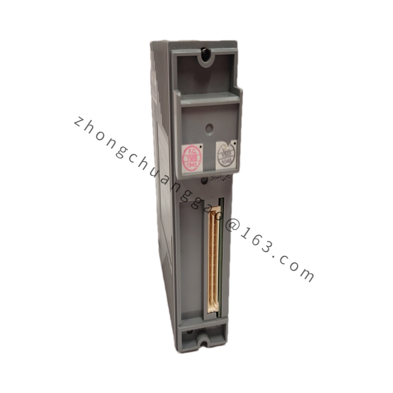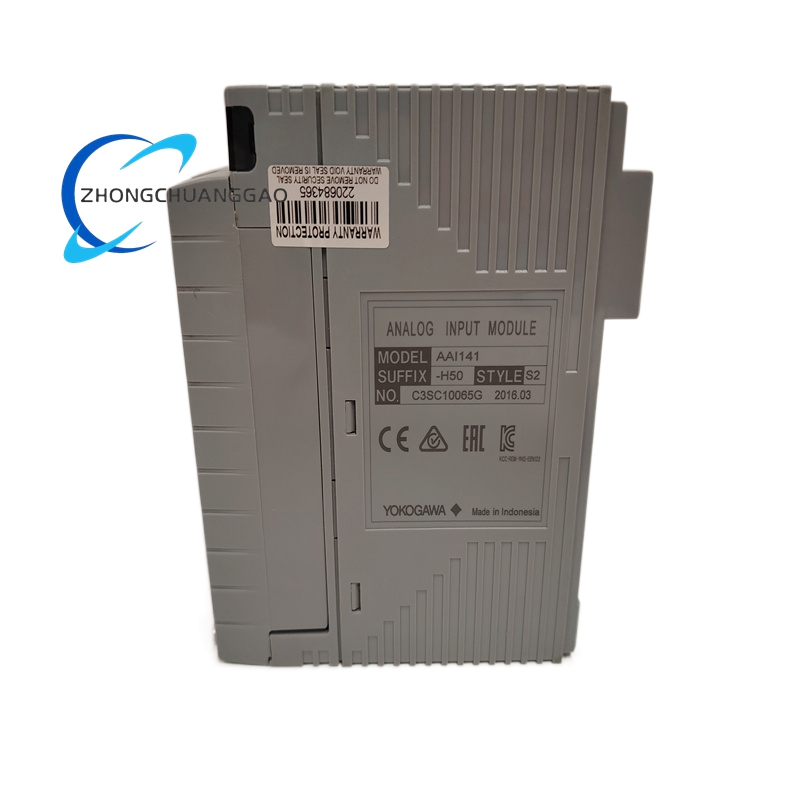


Product Overview:
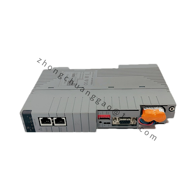
The DX2010-3-4-2 is a compact 96×96 mm panel-mount paperless recorder and controller from Yokogawa’s DXAdvanced series. It provides recording, display, and control functions in a DIN-standard front panel size. The unit supports 3 universal inputs, 4 isolated 4-20 mA outputs, and 2 alarm relay outputs, making it suitable for process monitoring and control applications.
Technical Specifications:
| Parameter | Value |
|---|---|
| Display | Monochrome LCD (128 × 64 dots) with LED backlight |
| Number of Input Channels | 3 channels (universal inputs) |
| Input Types | TC (J, K, T, E, R, S, B, N), RTD (Pt100, JPt100, Cu50), DC mA (0-10mA, 4-20mA), DC V (0-1V, 1-5V), DC mV (0-100mV) |
| Number of Output Channels | 4 channels (4-20 mA DC, isolated) |
| Number of Alarm Outputs | 2 channels (relay contact: 250V AC / 3A, 30V DC / 3A) |
| Recording Channels | 3 channels (simultaneous) |
| Recording Interval | 0.2 seconds to 60 minutes (adjustable) |
| Memory Capacity | Internal flash: approximately 2 MB (stores approximately 30 days at 1-second interval for 3 channels) |
| Communication Ports | RS-232C (9-pin D-sub), RS-485 (terminal block) |
| Communication Protocols | Modbus RTU (Master/Slave), Yokogawa CENTUM CS protocol (slave) |
| Additional Protocols | HART communication (optional, via HART mode on inputs) |
| Power Supply | 100-240 V AC, 50/60 Hz OR 24 V DC (dual power supply) |
| Power Consumption | Approximately 6 W (typical at 100 V AC) |
| Front Panel Size | 96 mm × 96 mm (DIN 96×96 standard, cutout: 92 mm × 92 mm) |
| Depth from Panel | Approximately 110 mm |
| Operating Temperature | 0°C to +50°C |
| Storage Temperature | -20°C to +70°C |
| Front Panel Protection | NEMA 4 / IP65 (from front) |
| Enclosure Material | Flame-retardant ABS plastic bezel, steel chassis |
| Weight | Approximately 0.8 kg |
| Isolation Voltage | Input to Output: 500 V AC, Output to Output: 250 V AC |
| Accuracy (Input) | ±0.2% of span (at 23°C ± 5°C) |
| Accuracy (Output) | ±0.1% of span (at 23°C ± 5°C) |
Functional Features:
Working Principle:
The DX2010-3-4-2 uses a 16-bit microprocessor with a high-resolution ADC (24-bit sigma-delta type) for each input channel. Signals are sampled, converted using stored calibration tables (including thermocouple reference junction compensation), and displayed on the monochrome LCD. Process data is written cyclically to internal flash memory. The 4-20 mA outputs are generated by 16-bit DACs with galvanic isolation. HART communication uses FSK (Frequency Shift Keying) modulation at 1200/2200 Hz superimposed on the 4-20 mA signal.
Advantages and Highlights:
Applicable Industries:
Installation Requirements:
Usage Precautions: