
Digital guide

You are here:

YOKOGAWA B9317PA

Product Series: CENTUM CS/VP System I/O Terminal Assemblies

Product Introduction:
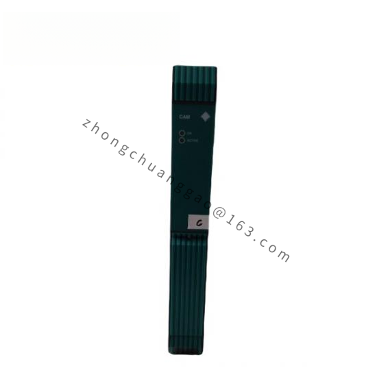
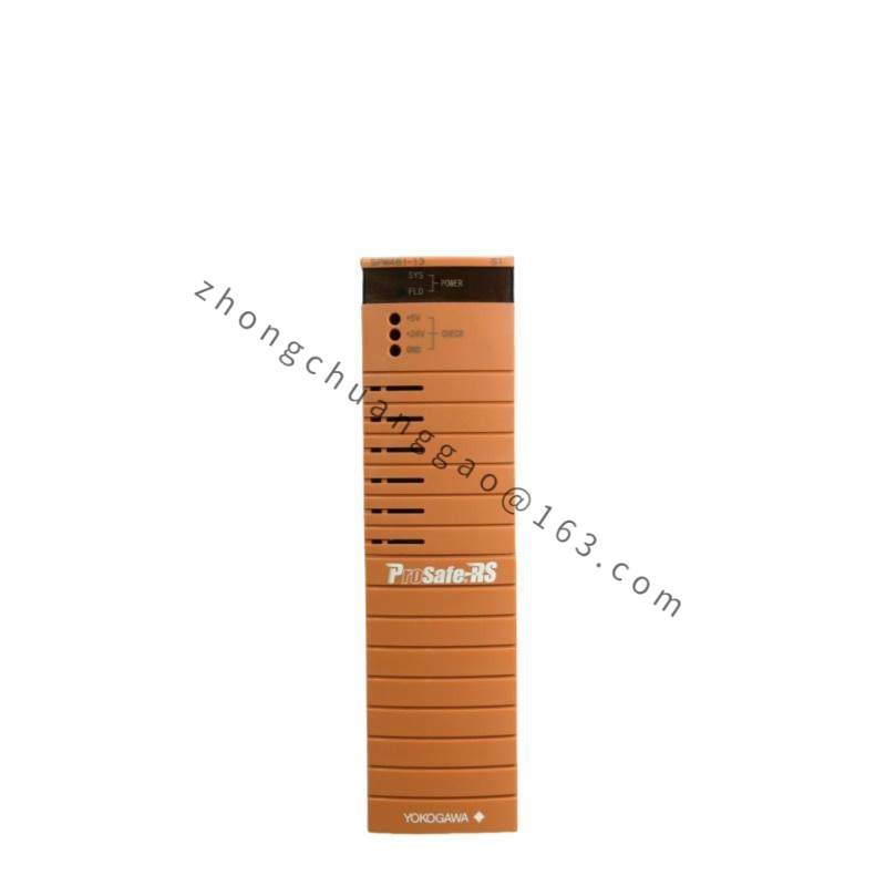
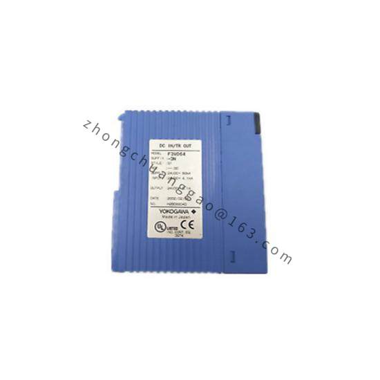
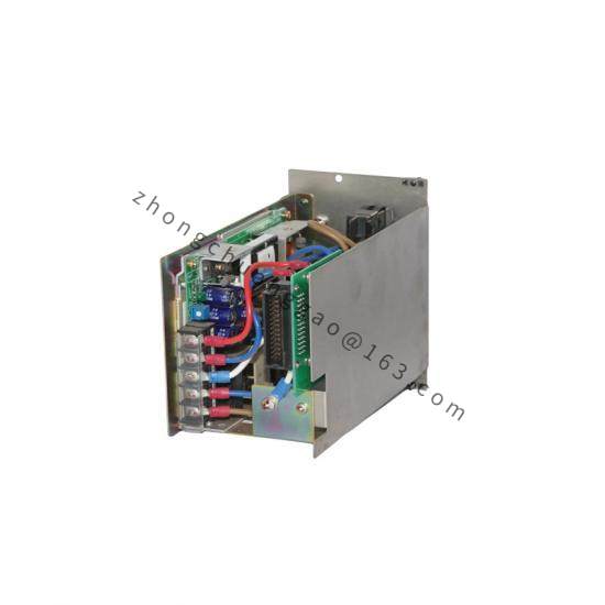
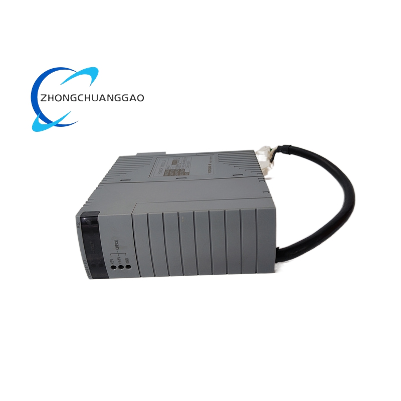
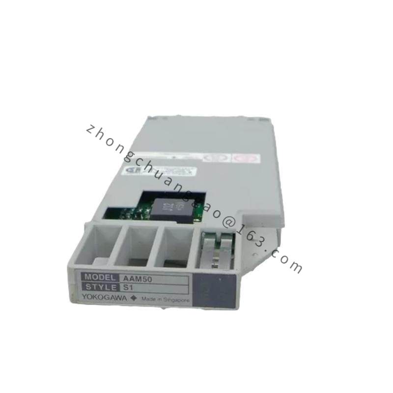
The B9317PA is an I/O terminal block (wiring board) used in Yokogawa CENTUM CS 3000 and CENTUM VP distributed control systems. It provides the physical connection interface between field instruments and the DCS I/O cards.

Detailed content

Technical Specifications:

  • Product TypeI/O Wiring Terminal Block
  • Compatible SystemsCENTUM CS 3000, CENTUM VP, CENTUM XL
  • Terminal Type: Spring-clamp terminal blocks (push-in type)
  • Wire Gauge Compatibility: 0.5 mm² to 2.5 mm² (22 AWG to 14 AWG)
  • Number of Terminals16 terminals per block (standard configuration)
  • Rated Voltage250 VAC / 30 VDC
  • Rated Current8 A per terminal
  • Insulation Resistance: ≥ 100 MΩ at 500 VDC
  • Dielectric Strength1500 VAC for 1 minute
  • Housing Material: Flame-retardant polycarbonate (UL94 V-0 rated)
  • Contact MaterialPhosphor bronze with tin plating
  • Operating Temperature: -10°C to +60°C (+14°F to +140°F)
  • Dimensions (W × H × D): Approximately 150 mm × 30 mm × 80 mm (varies by configuration)
  • Weight: Approximately 0.15 kg

Functional Features:

  • Spring-clamp termination eliminates need for screwdriver — enables fast wiring
  • Color-coded terminal positions match DCS I/O card channel assignments
  • Test points available for each channel for field verification
  • DIN rail mountable within the DCS I/O cabinet

Structural Features:

  • Modular plastic housing with label strip for channel identification
  • Individual spring-clamp terminals per channel
  • DIN rail (TS35) mounting clips on rear
  • Keyed connector for mating with DCS I/O card backplane

Working Principle:
Field instrument wires (thermocouple, RTD, 4–20 mA, etc.) are inserted into the spring-clamp terminals. The spring mechanism provides gas-tight contact without screw tightening. The terminal block routes the signals to the corresponding DCS I/O card via the backplane connector. Test points allow technicians to inject calibration signals or measure loop current without disconnecting wires.

Advantages & Highlights:

  • Spring-clamp technology reduces wiring time by up to 50% compared to screw terminals
  • UL94 V-0 flame-retardant housing meets fire safety requirements
  • Color-coded layout minimizes wiring errors during installation and maintenance
  • Test points per channel enable on-line loop verification

Applicable Industries:

  • Oil and gas (onshore and offshore platforms)
  • Petrochemical refineries
  • Power generation (thermal, nuclear, renewable)
  • Pulp and paper mills
  • Steel and metal processing

Installation Requirements:

  • Mount on DIN rail inside the DCS I/O cabinet
  • Ensure wire stripping length matches the spring-clamp specification (8–10 mm)
  • Verify wire gauge is within 0.5–2.5 mm² range
  • Label all wires per the DCS I/O assignment drawing before termination

Usage Precautions:

  • Do not use wire gauges outside the 0.5–2.5 mm² range — will damage the spring contact
  • Do not apply more than 30 VDC / 250 VAC to any terminal
  • Tighten the DIN rail mounting clips securely to prevent vibration-induced disconnection
  • Replace the terminal block if any spring contact shows signs of fatigue or corrosion

You may also like