

Digital guide

You are here:

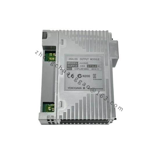
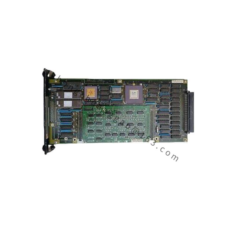
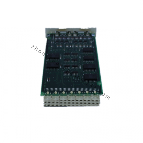
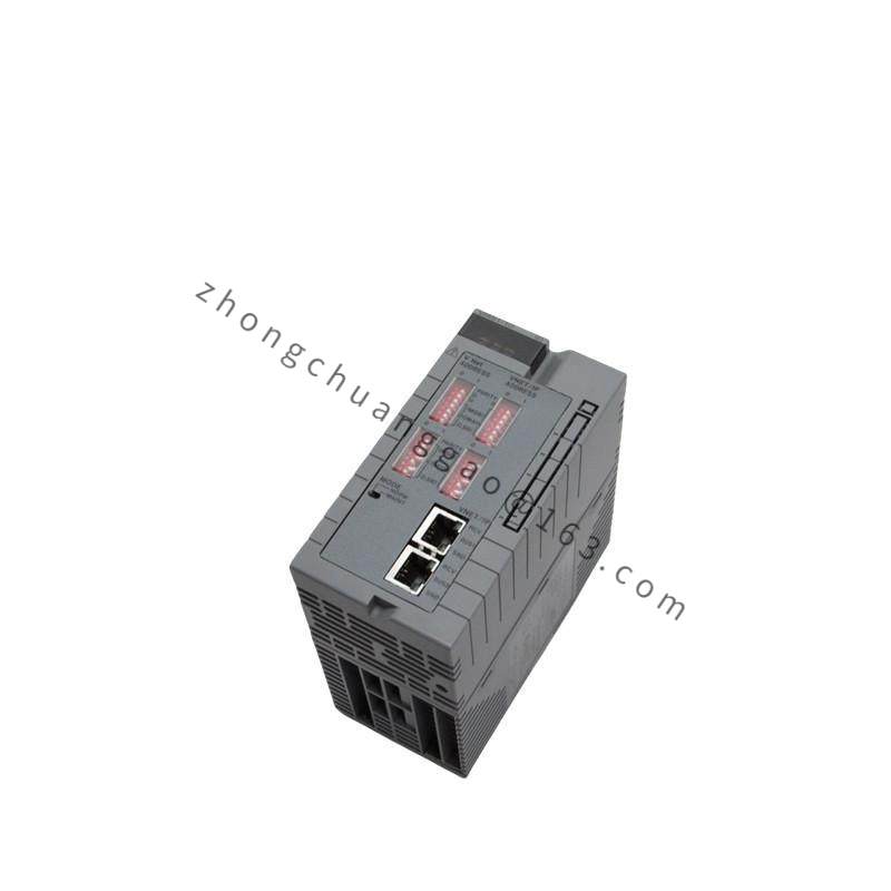
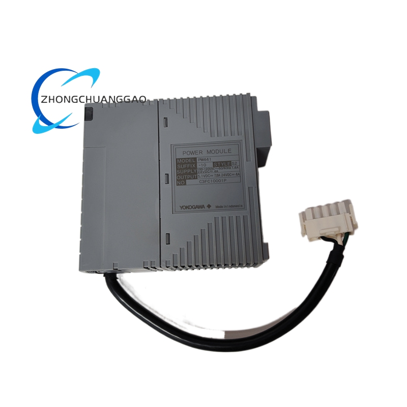
Yokogawa ANB10D-420/CU2T/NDEL

Product Introduction:
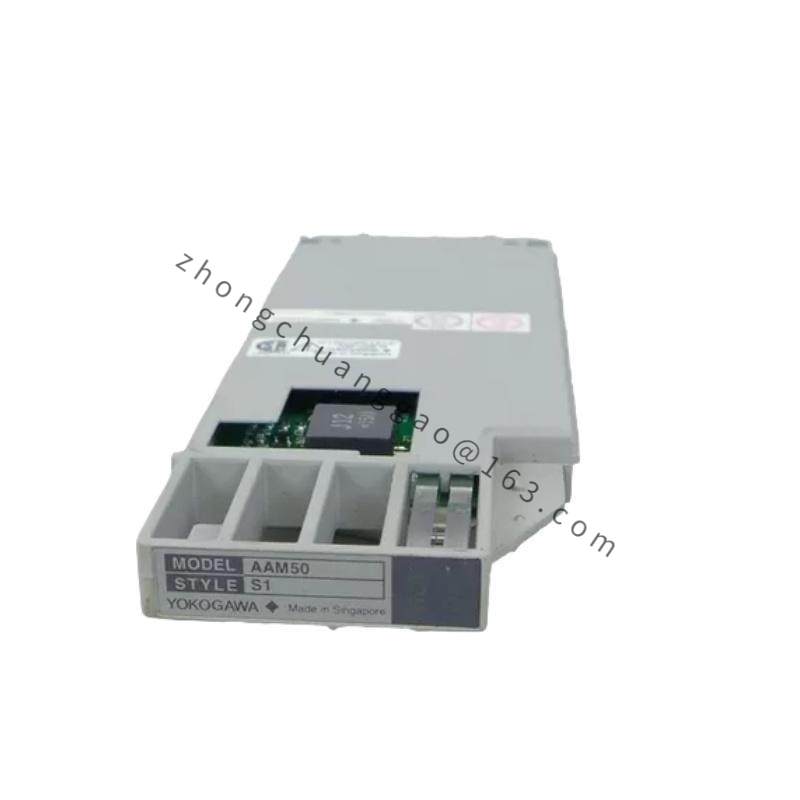
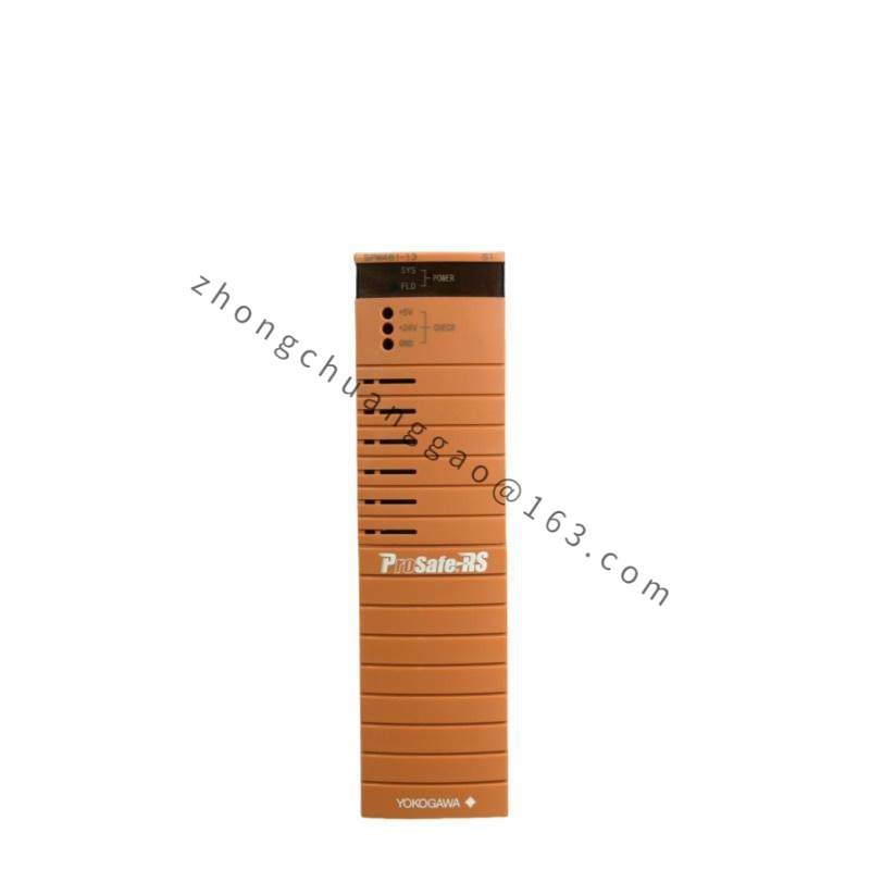
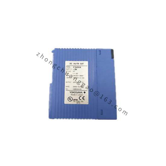
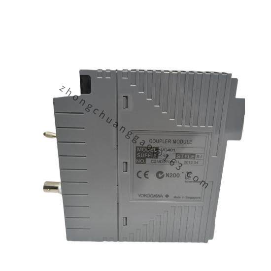
The ANB10D-420/CU2T/NDEL is a 10-channel analog input module from Yokogawa’s F3 I/O series, designed for use in CENTUM VPCENTUM CS 3000, and ProSafe-RS safety systems. It accepts 4–20 mA DC current signals from field transmitters and digitizes them for transmission over the F Fieldbus (H1) or Modbus RTU communication network. The CU2T designation indicates a copper terminal block wiring configuration, and NDEL specifies the non-delay (fast scan) processing mode.

Detailed content

Model Number Breakdown:

  • ANB10D: 10-channel analog input, DCS-compatible
  • 420: Input range 4–20 mA DC
  • CU2TCopper screw terminal connection type
  • NDELNo delay (fast update, non-filtered) mode

Key Specifications:

  • Number of Channels: 10 channels (single-ended or differential selectable)
  • Input Signal4–20 mA DC (2-wire transmitter powered)
  • Input Impedance250 Ω (burden voltage ≤ 5 V at 20 mA)
  • Resolution: 16-bit A/D converter (65,536 steps)
  • Conversion Time: 1 ms per channel (NDEL mode)
  • Accuracy: ±0.1% of span (at 25 °C)
  • Common Mode Rejection Ratio (CMRR)≥ 120 dB (at 50/60 Hz)
  • Isolation Voltage1500 V AC between channels and between channels and bus
  • Communication: F Fieldbus H1 (31.25 kbps) / Modbus RTU (RS-485)
  • Power Consumption: ≤ 3.5 W per module

Functional Features:

  • Channel-by-Channel Configuration: Each of the 10 channels can be independently configured for input range, filtering, and alarm limits
  • Fail-Safe Output: Configurable high/low/hold-last behavior on communication failure
  • Burnout Detection: Detects open circuit (> 22 mA) and short circuit (< 3.8 mA) conditions
  • Self-Diagnosis: Continuous monitoring of A/D converter, communication, and internal circuitry
  • LED Indicators: Per-channel green (normal) and red (alarm/fault) status LEDs

Material Composition:

  • Housing: Glass-fiber reinforced PBT plastic (UL94 V-0, flame retardant)
  • Terminal Blocks: Copper alloy with tin plating (CU2T specification)
  • PCB: FR-4 epoxy glass with conformal coating
  • Connector: F Fieldbus H1 connector (9-pin D-sub, shielded)

Structural Characteristics:

  • Form Factor: DIN rail-mountable, 16 mm width per module slot
  • Dimensions129.5 mm (W) × 130 mm (H) × 120 mm (D) (approximate, including terminals)
  • Weight: Approximately 0.45 kg

Operating Principle:
Each input channel receives a 4–20 mA current signal from a field transmitter. The current flows through a precision 250 Ω burden resistor, generating a 1–5 V voltage proportional to the input. This voltage is fed into a 16-bit successive approximation A/D converter. The digital value is then packaged into F Fieldbus function blocks or Modbus registers and transmitted to the DCS controller. In NDEL mode, the conversion result is transmitted immediately without software filtering, enabling fast process response.

Advantages & Highlights:

  • High-Speed Scanning: NDEL mode provides 1 ms update rate per channel — ideal for fast-response processes
  • Wide CMRR≥ 120 dB rejection of common-mode noise ensures signal integrity in electrically noisy environments
  • Robust Isolation: 1500 V AC isolation protects the DCS from field-side transients
  • Flexible Wiring: CU2T copper terminal block allows secure, tool-free wiring in the field

Applicable Industries:

  • Chemical Processing
  • Oil & Gas Production
  • Power Generation (Boiler/Turbine Control)
  • Pharmaceutical Manufacturing
  • Pulp & Paper

Installation Requirements:

  • Install in a DIN rail enclosure with adequate ventilation; maintain ambient temperature 0 to 55 °C
  • Use shielded twisted-pair cable for all 4–20 mA input signals; connect shield to chassis ground at one end only
  • Maximum cable length from transmitter: 1000 m (depending on wire gauge and load)
  • Ensure 24 V DC loop power supply is available for 2-wire transmitters (≤ 5 V burden)

Usage Precautions:

  • Do not exceed 30 V DC across any input channel (including transient spikes)
  • Verify transmitter is 2-wire, loop-powered (4–20 mA) type; 4-wire transmitters require external power
  • Do not mix input types (e.g., mA and mV) on the same module — use dedicated modules per signal type
  • Periodically verify terminal screw torque: 0.5–0.8 N·m

You may also like