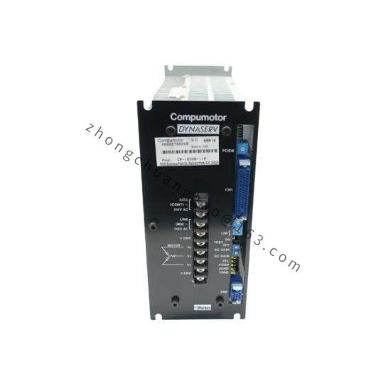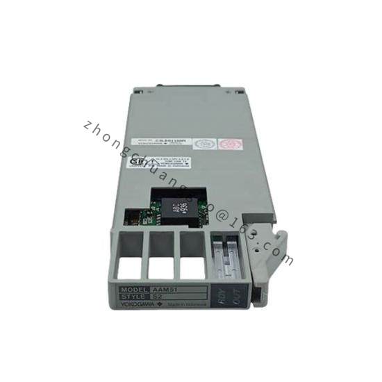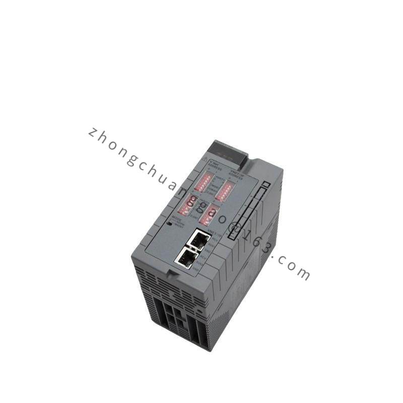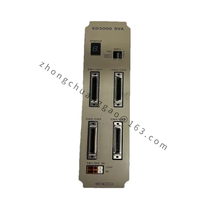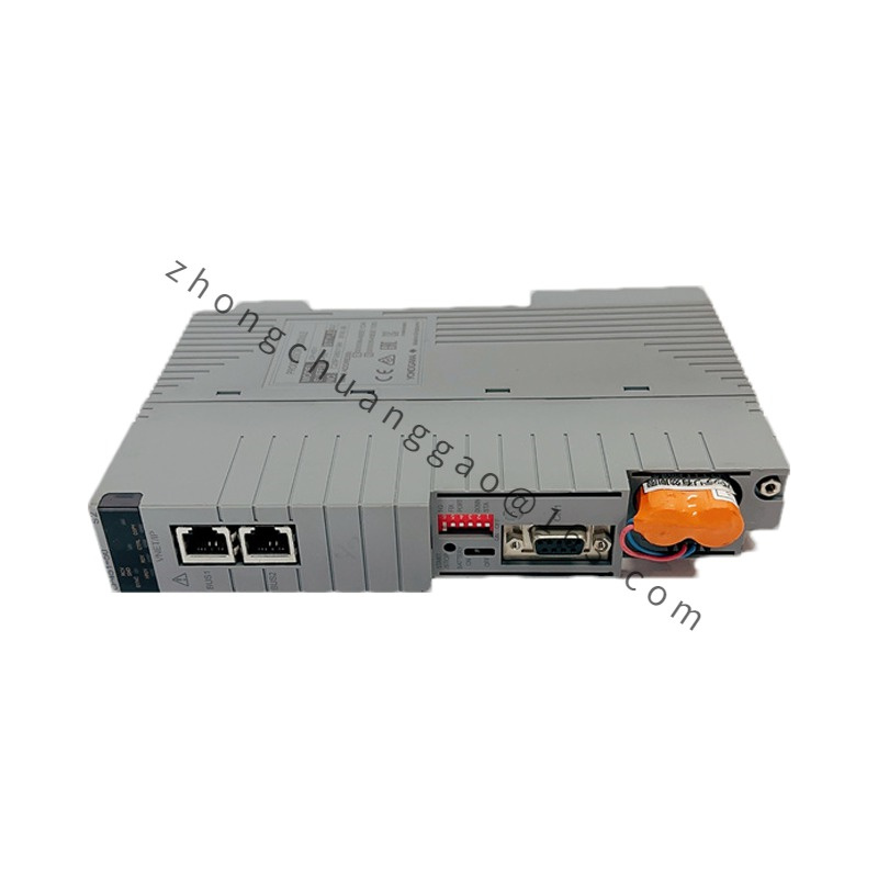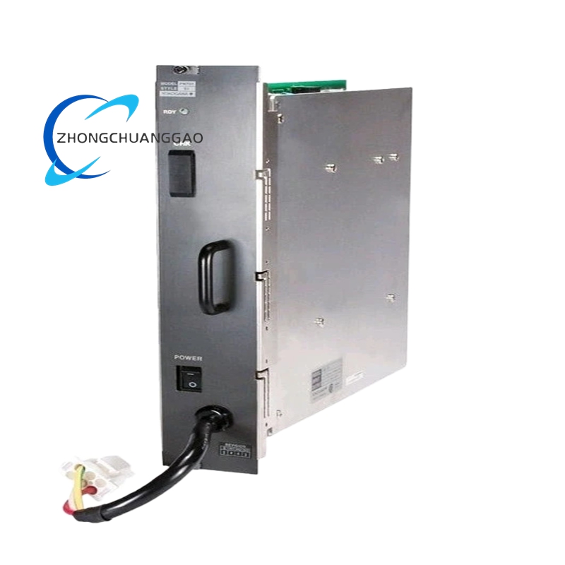
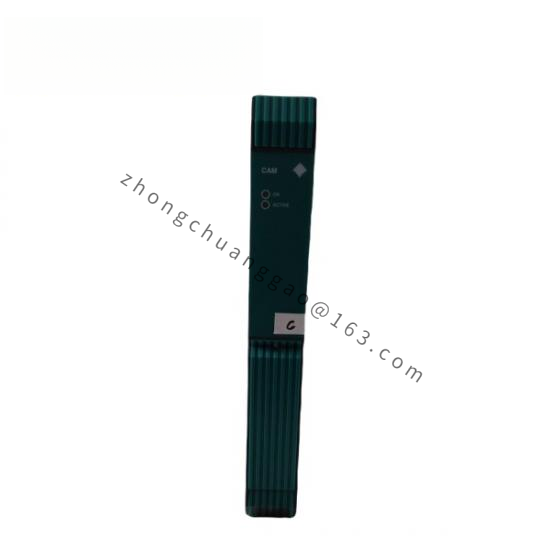
Yokogawa ACM12-S1
Product Type: 4-Channel Analog Current (4–20 mA) Input Module
Product Overview:
The Yokogawa ACM12-S1 is a 4-channel analog input module for the Yokogawa FAI (Fieldbus Interface) and CENTUM series DCS systems. It accepts 4–20 mA DC input signals and converts them to digital values for the DCS controller. The “S1” designation indicates the standard accuracy version with 16-bit resolution.
Detailed content
Technical Specifications:
- Number of Channels: 4 channels
- Input Signal: 4–20 mA DC (2-wire or 4-wire)
- Input Impedance: 250 Ω (burden resistor, built-in)
- Resolution: 16 bits (65,536 steps)
- Conversion Time: 100 ms per channel (400 ms total for 4 channels)
- Accuracy: ±0.1% of span
- Common Mode Rejection: ≥ 100 dB (50/60 Hz)
- Isolation: 1500 V AC between channels and between channels and backplane (1 minute)
- Power Supply: 5 V DC from backplane bus
- Operating Temperature: 0°C to 55°C
- Dimensions: 25 × 120 × 120 mm (W × H × D) (single-width module)
- Weight: Approximately 0.15 kg
- Certification: CE, UL, CSA
Functional Features:
- Per-channel input range configuration (4–20 mA, 0–20 mA, 0–10 mA via jumper)
- Per-channel linearization (up to 10 points)
- Per-channel alarm setpoints (HH, H, L, LL)
- Per-channel input filter (0.1 to 10 seconds, configurable)
- LED indicators per channel (power, alarm, communication)
- Hot-swappable design
Performance Parameters:
- Linearity: ±0.05% of span
- Temperature Coefficient: ±10 ppm/°C
- Dielectric Withstand Voltage: 1500 V AC, 1 minute
- EMC Compliance: IEC 61000-6-2, IEC 61000-6-4
- MTBF: > 200,000 hours (at 25°C)
Material Composition:
- Module body: FR-4 epoxy glass PCB with conformal coating
- Connector: 40-pin edge connector (gold-plated)
- Terminal block: Phoenix Contact-compatible screw terminals (wire gauge: 22–14 AWG)
- Housing: ABS resin (UL94 V-0)
Structural Features:
- Standard DIN rail module (1/4 width)
- Front-panel terminal block with channel identification labels
- LED status indicators per channel
- DIP switches or software configuration for range and filter settings
- Locking mechanism for secure backplane insertion
Working Principle:
The 4–20 mA input signal flows through the 250 Ω burden resistor, creating a voltage drop of 1–5 V. This voltage is amplified by an instrumentation amplifier and fed to a 16-bit delta-sigma ADC. The ADC converts the analog voltage to a digital value, which is processed by the module’s FPGA. The FPGA applies per-channel linearization, filtering, and scaling. The digital value is transmitted to the DCS controller via the backplane bus. Alarm logic compares the value against user-set limits and triggers a status flag on the backplane.
Advantages & Highlights:
- 16-bit resolution provides high measurement precision
- 1500 V AC isolation ensures noise immunity and safety
- Per-channel configurability eliminates need for external signal conditioners
- Hot-swappable design enables replacement without system shutdown
- Compact 1/4-width module saves rack space
Applicable Industries:
- Oil and gas (refinery, pipeline, offshore)
- Chemical and petrochemical
- Power generation and distribution
- Pulp and paper
- Pharmaceutical
- Water and wastewater
Installation Requirements:
- Insert the module into a CENTUM VP or CENTUM CS I/O carrier
- Ensure the backplane bus voltage is stable at 5 V DC ±5%
- Connect 4–20 mA signals to the terminal block (observe polarity: + to +, – to –)
- Use shielded twisted-pair cables; ground the shield at the DCS end only
- Configure the input range and filter via the DCS engineering station before commissioning
Usage Precautions:
- Do not apply voltage exceeding 30 V DC to the input terminals
- Do not disconnect or connect input signals while the DCS is running (if not hot-swap rated)
- Verify the input signal is within the configured range before enabling the channel
- Replace the module if the accuracy degrades beyond ±0.1% of span
- Keep the module free from conductive dust and excessive humidity
Yokogawa AX01C-C005/CH
Product Name: Yokogawa AX01C-C005/CH Charge Input Module
Model Series: AX01C Series
Product Type: 2-Channel Charge Input Module for Piezoelectric Sensors
Product Overview:
The Yokogawa AX01C-C005/CH is a 2-channel charge input module designed for connection to piezoelectric sensors such as accelerometers and force transducers. The “C005” specifies the charge sensitivity range (5 pC/unit), and “/CH” indicates the China regional variant with Chinese documentation and certification. It is used in CENTUM DCS and FAI systems for vibration, force, and pressure measurement.
Technical Specifications:
- Number of Channels: 2 channels
- Input Signal: Charge (pC) from piezoelectric sensors
- Charge Sensitivity Range: 5 pC/unit (C005), 50 pC/unit (C050), 500 pC/unit (C500) — selectable via jumper
- Input Impedance: > 10¹³ Ω (charge mode)
- Resolution: 20 bits
- Conversion Time: 50 ms per channel (100 ms total)
- Accuracy: ±0.5% of span
- Linearity: ±0.1% of span
- Common Mode Rejection: ≥ 120 dB (50/60 Hz)
- Isolation: 500 V AC between channels, 1500 V AC to backplane (1 minute)
- Low-Pass Filter: 0.5 Hz to 20 kHz (configurable per channel)
- Power Supply: 5 V DC from backplane bus
- Operating Temperature: 0°C to 55°C
- Dimensions: 25 × 120 × 120 mm (W × H × D) (single-width module)
- Weight: Approximately 0.18 kg
- Certification: CE, CCC (China Compulsory Certification)
Functional Features:
- 2 independent charge input channels
- Per-channel charge sensitivity selection (5/50/500 pC)
- Per-channel low-pass filter configuration
- Per-channel alarm setpoints (HH, H, L, LL)
- Per-channel sensor fault detection (open circuit, short circuit)
- LED indicators per channel (power, alarm, sensor fault)
- Hot-swappable design
Performance Parameters:
- Noise Level: < 0.02 pC RMS (at 5 pC range)
- Temperature Coefficient: ±5 ppm/°C
- Dielectric Withstand Voltage: 1500 V AC, 1 minute
- EMC Compliance: IEC 61000-6-2, IEC 61000-6-4
- MTBF: > 200,000 hours (at 25°C)
Material Composition:
- Module body: FR-4 epoxy glass PCB with conformal coating
- Connector: 40-pin edge connector (gold-plated)
- Terminal block: Screw terminals for charge signal input (triaxial connector recommended for low-noise applications)
- Housing: ABS resin (UL94 V-0, China CCC rated)
- Shielding: Metal can around the input amplifier section
Structural Features:
- Standard 1/4-width DIN rail module for CENTUM VP/CS I/O carriers
- Front-panel terminal block with channel labels
- Triaxial BNC connector option for low-noise sensor connection
- DIP switches for range and filter configuration
- LED indicators: Power (green), Alarm (red), Sensor Fault (amber) per channel
Working Principle:
The piezoelectric sensor generates a charge (in picocoulombs) proportional to the measured physical quantity (acceleration, force, or pressure). The charge is transmitted via a low-noise cable to the AX01C input. The module’s ultra-high-impedance charge amplifier (input impedance > 10¹³ Ω) converts the charge to a voltage. A 20-bit delta-sigma ADC digitizes the voltage. The FPGA applies per-channel filtering, linearization, and scaling. The digital value is sent to the DCS controller via the backplane bus. The sensor fault detection circuit monitors the input for open-circuit (infinite impedance) and short-circuit (zero impedance) conditions.
Advantages & Highlights:
- 20-bit resolution provides exceptional measurement precision for low-level charge signals
- Ultra-high input impedance (> 10¹³ Ω) preserves the charge signal without leakage
- Per-channel filter configuration eliminates noise and aliasing
- Sensor fault detection prevents false readings from disconnected or shorted sensors
- Hot-swappable design allows module replacement without system shutdown
- China CCC certification for use in Chinese industrial facilities
Applicable Industries:
- Machinery vibration monitoring (turbines, compressors, motors, pumps)
- Force measurement in manufacturing processes
- Piezoelectric pressure sensing
- Structural health monitoring
- Aerospace and defense (test and measurement)
- Automotive (engine and chassis dynamometer testing)
Installation Requirements:
- Insert the module into a CENTUM VP or CENTUM CS I/O carrier slot
- Connect piezoelectric sensors using low-noise triaxial cables (central conductor: signal, inner shield: driven guard, outer shield: ground)
- Ground the cable shield at the module end only (single-point grounding)
- Configure the charge sensitivity range (5/50/500 pC) to match the sensor output
- Set the low-pass filter cutoff frequency based on the maximum frequency of interest (e.g., 10 kHz for bearing fault detection)
Usage Precautions:
- Do not touch the input terminals with bare hands (body static can damage the high-impedance input)
- Do not exceed the maximum charge input (typically 100,000 pC) — use the C500 range for high-output sensors
- Use triaxial cable with driven guard for sensors located more than 5 meters from the module
- Verify sensor polarity before connecting (reverse polarity inverts the signal)
- Perform a zero-offset check with the sensor unloaded before commissioning
- Replace the module if the noise floor exceeds 0.05 pC RMS