
Yokogawa AAXF010C-D1CE-GUN1-01A
Product Introduction:
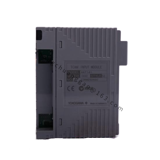
The AAXF010C-D1CE-GUN1-01A is a signal isolator and converter from Yokogawa’s AAXF series, designed to isolate, convert, and condition analog signals in industrial automation and process control applications. It provides galvanic isolation between input and output circuits, protecting sensitive DCS/PLC inputs from field-side electrical noise, ground loops, and high-voltage transients. The unit supports multiple input and output signal types with DIN rail mounting.
Detailed content
Model Number Breakdown:
- AAXF: Analog signal isolator/converter series
- 010C: 1-input, 1-output configuration; C = current input/output type
- D1CE: Input: DC voltage (0–10 V); Output: DC current (4–20 mA)
- G: Ground-isolated (input ground independent of output ground)
- U: Universal power supply (85–265 V AC/DC)
- N1: NEMA 4 / IP65 front panel (or specific configuration code)
- 01A: Revision / firmware version
Key Specifications:
- Number of Channels: 1 input, 1 output (isolated)
- Input Signal: DC 0–10 V (from model code D1)
- Output Signal: DC 4–20 mA (from model code CE)
- Isolation Voltage: 1500 V AC (input-to-output); 1500 V AC (input-to-power); 1500 V AC (output-to-power) — triple isolation
- Accuracy: ±0.1% of span (at 25 °C)
- Linearity: ±0.05% of span
- Temperature Drift: ±0.005% of span per °C
- Response Time: ≤ 10 ms (typical)
- Power Supply: 85–265 V AC/DC (universal)
- Power Consumption: ≤ 2.5 W
- Operating Temperature: -10 to +50 °C
- Protection Rating: IP20 (DIN rail mounting); front panel IP65 option available
- Communication: None (standalone analog device)
Functional Features:
- Triple Galvanic Isolation: Complete electrical separation between input, output, and power — eliminates ground loops entirely
- Signal Conversion: Converts DC 0–10 V to DC 4–20 mA (or other combinations per configuration)
- Burnout Detection: Detects open circuit (> 22 mA) and short circuit (< 3.5 mA) on the output side
- Reverse Polarity Protection: Input and output are protected against reverse polarity connection
- DIN Rail Mounting: Standard 35 mm DIN rail installation
Material Composition:
- Housing: Flame-retardant PC/ABS blend (UL94 V-0)
- PCB: FR-4 epoxy glass with conformal coating (silicone)
- Terminal Blocks: Phosphor bronze with tin plating; spring-loaded clamp type
- DIN Rail Clip: Zinc-plated steel
Structural Characteristics:
- Form Factor: DIN rail-mountable module
- Dimensions: 22.5 mm (W) × 115 mm (H) × 115 mm (D) (1 module width)
- Weight: Approximately 0.15 kg
- Terminal Connection: Spring-clamp terminal blocks (no screwdriver required)
Operating Principle:
The input signal (0–10 V DC) is first conditioned by an input amplifier with high input impedance (> 1 MΩ) to prevent loading of the field source. The conditioned signal is then converted to a digital representation by a 16-bit A/D converter. A digital isolation barrier (optical or transformer-based) transfers the digital data across the 1500 V AC isolation barrier to the output side. On the output side, a 16-bit D/A converter reconstructs the analog signal, which is then converted to a 4–20 mA current output by a precision voltage-to-current converter with Howland current pump topology. The triple isolation ensures that no electrical path exists between input, output, and power circuits.
Advantages & Highlights:
- Complete Ground Loop Elimination: Triple isolation breaks all ground loop paths — critical for multi-ground installations
- High Accuracy: ±0.1% of span — suitable for precision measurement applications
- Universal Power: 85–265 V AC/DC — works worldwide without transformer
- Fast Response: ≤ 10 ms — suitable for dynamic process signals
Applicable Industries:
- Industrial Automation (OEM Machines)
- Process Control (DCS/PLC Signal Conditioning)
- Building Automation (HVAC)
- Power Generation (Turbine/Generator Monitoring)
- Water & Wastewater
- Marine & Offshore
Installation Requirements:
- Mount on standard 35 mm DIN rail inside a control cabinet
- Connect input wiring to the input terminal block; connect output wiring to the output terminal block
- Ensure power supply voltage is within 85–265 V AC/DC range
- Maintain minimum 10 mm spacing between modules for heat dissipation
- Ground the DIN rail to the cabinet earth bus
Usage Precautions:
- Verify input signal range matches the configured type (0–10 V DC in this case) before energizing
- Do not exceed 30 V DC on the input terminals (even with isolation, transient protection has limits)
- Do not connect the input ground to the output ground — this defeats the isolation purpose
- Check LED status indicators (power: green; fault: red) after installation
- Do not operate in ambient temperatures below -10 °C or above +50 °C