Technical Specifications
|
Parameter
|
Specification
|
|
Relay channels
|
16
|
|
Contact form
|
Form A, normally open
|
|
Contact rating
|
2 A at 250 V AC resistive
|
|
Coil-to-contact isolation
|
1500 V AC
|
|
Power dissipation
|
Approximately 3 W
|
|
Operate time
|
Less than 10 ms
|
|
Electrical life
|
100,000 operations
|
|
Operating temperature
|
0 °C to 60 °C
|
|
Hot-swap support
|
Supported in qualified CENTUM node configuration
|
|
Status indication
|
Per-channel relay LEDs and module fault indication
|
Functional Features
Sixteen independently driven alarm relays provide galvanic separation between control bus and field devices. Front LEDs show channel and health status. Built-in test function validates relay operation without external trip simulation. Isolation reduces noise coupling from inductive field loads.
Application Scenarios
Used for process alarm annunciation in refineries and petrochemical plants, turbine/boiler alarm panels in power stations, shutdown horn and beacon control in manufacturing facilities, pump-fault signaling in water/wastewater stations and hardwired interlocks in pharmaceutical and food plants.
Performance Parameters
Contact switching handles 2 A resistive at 250 V AC. Operate time is under 10 ms for typical alarm transfer. Isolation testing is 1500 V AC between coil circuit and contact circuit. Power loss is low enough for dense CENTUM I/O mounting when ventilation follows rack rules.
Material Composition
Flame-retardant plastic housing, silver-alloy relay contacts, FR4 control PCB, tin-plated copper field terminals and gold-plated backplane connector contacts.
Structural Characteristics
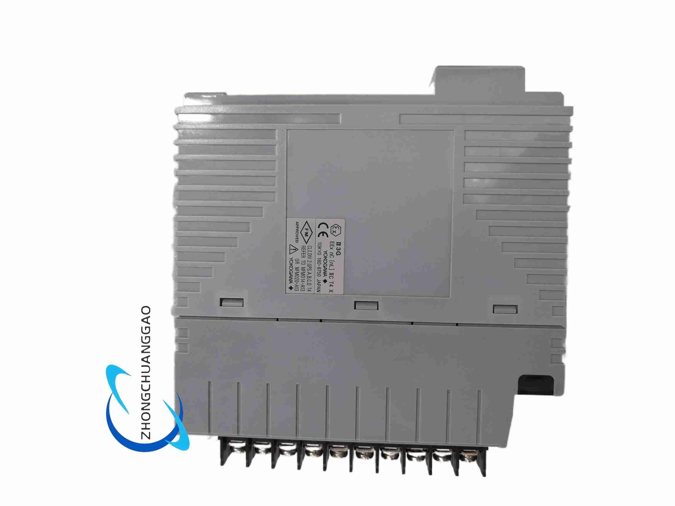
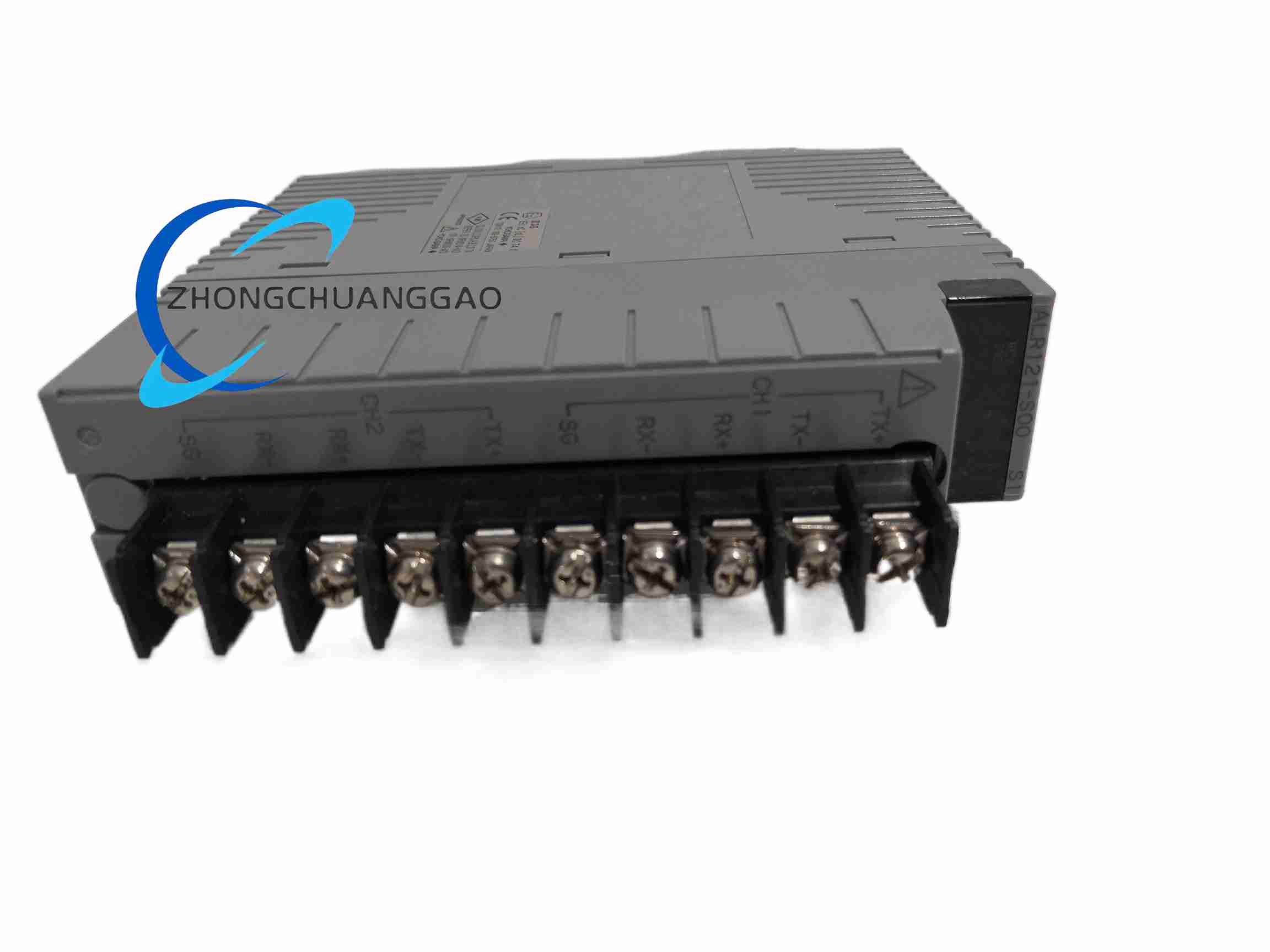
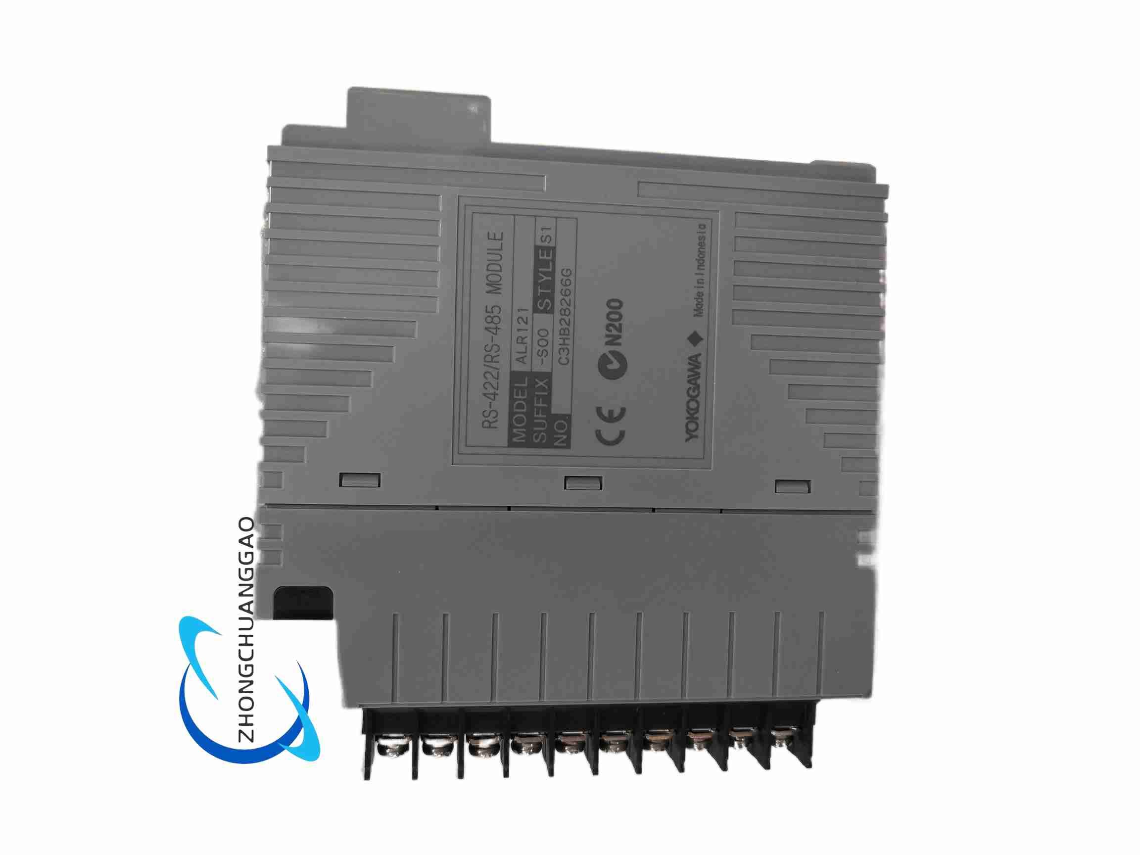
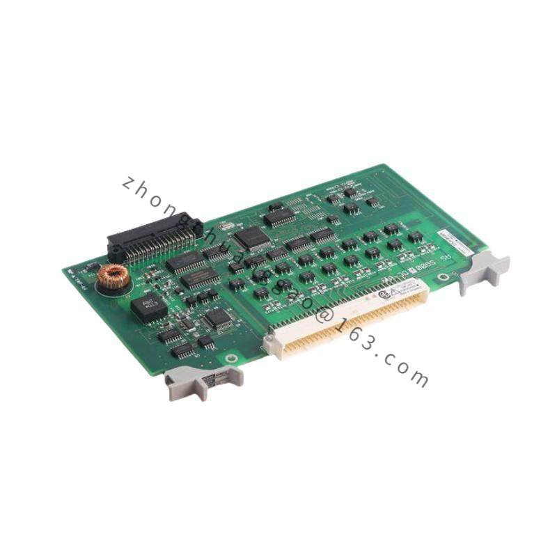
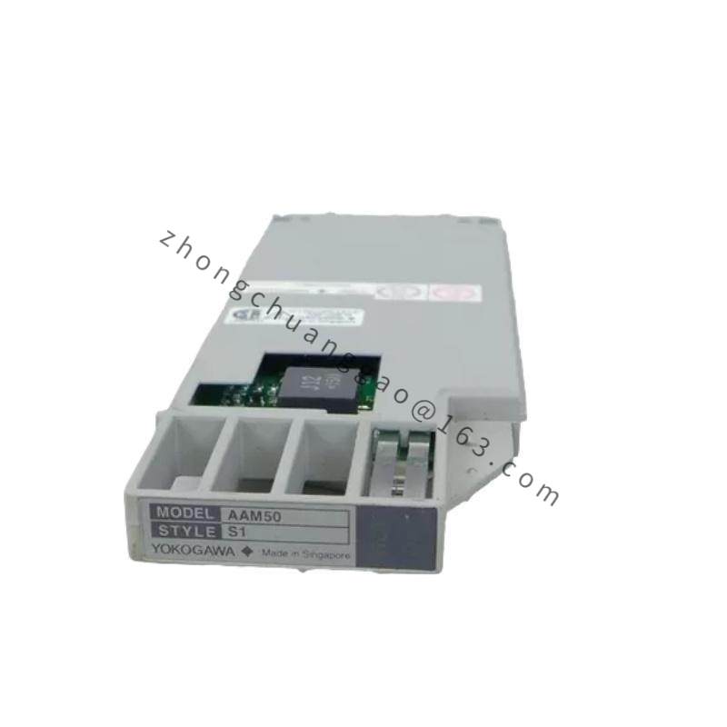
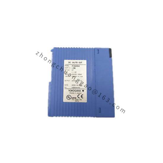
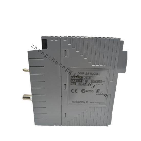
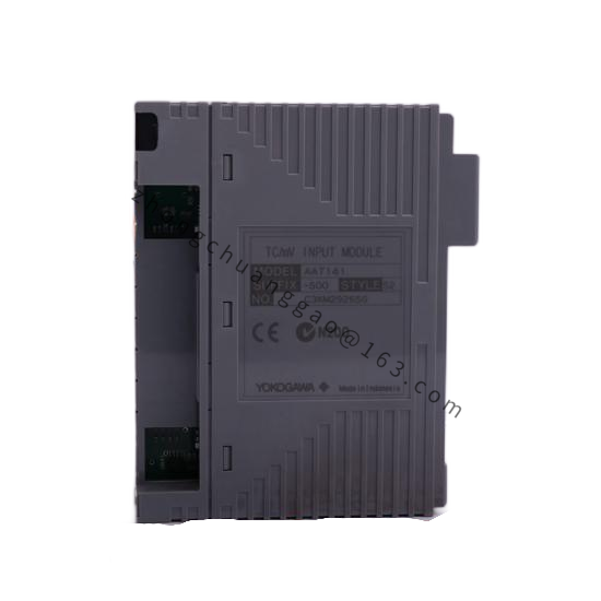
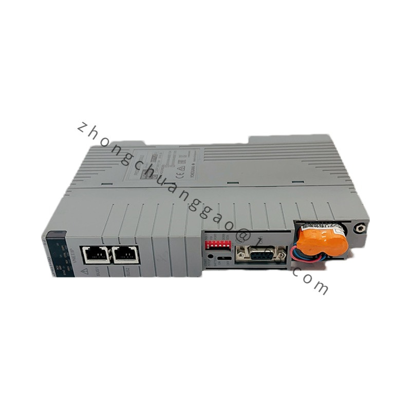
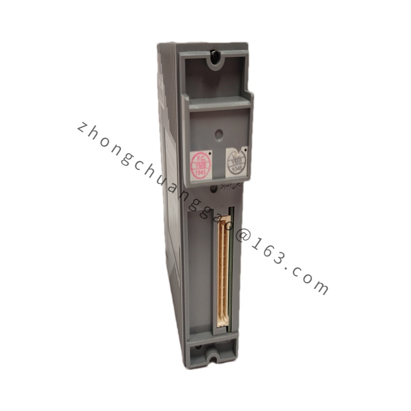
Standard CENTUM plug-in module with front status LEDs, rear backplane connector, card guide rails, locking latches and separate alarm field wiring through the associated terminal base.
Working Principle
The controller sends alarm or interlock status to the module logic. The driver energizes the corresponding relay coil, creates a magnetic path that closes the Form A contact, and connects the external annunciator, solenoid or shutdown circuit. De-energizing opens the contact and clears the output.
Installation Requirements
Install in the designated CENTUM alarm relay I/O slot and seat the backplane connector fully. Wire alarm circuits through the matched terminal base using conductors rated for the contact load. Provide surge suppression for inductive horns, solenoids or valve coils. Verify rack cooling and slot assignment before power-up.
Usage Precautions
Do not exceed 2 A at 250 V AC resistive on each contact. Use suppression diodes or RC snubbers for DC inductive loads and RC/snubber for AC inductive loads. Test relay operation during commissioning and after any controller alarmlogic change. Replace the terminal base if contact welding, overheating or repeated nuisance alarms are observed.