Technical Specifications
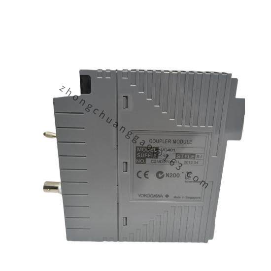
Manufacturer: Yokogawa.
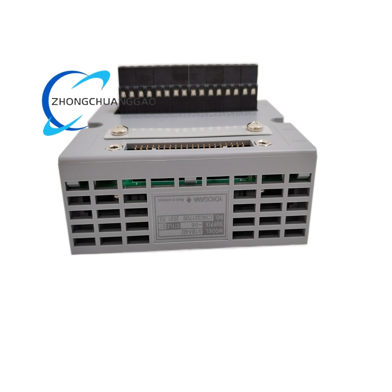
Model: A1BA4D 05.
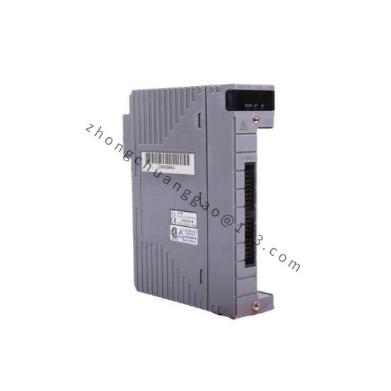
Product type: analog terminal board.
Channel configuration: A1BA4D family supports 16 channel single unit or 8 channel configurations according to model and system design.
Redundancy: single and dual redundant versions are listed for the A1BA4D family.
Suffix 05 definition: basic type without explosion protection according to the listed ordering information.
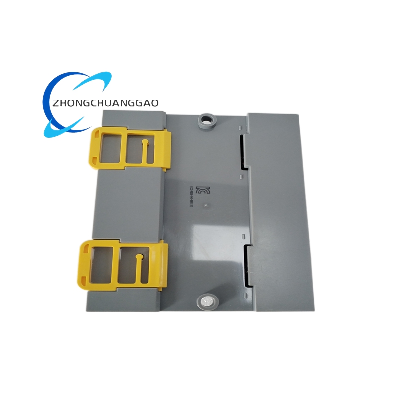
Mounting: DIN rail mount type.
Shipping weight: approximately 3 kg.
Functional Features
Centralizes analog field wiring into a controlled termination point.
Supports organized channel grouping for transmitters and controllers.
DIN rail format for standard control cabinet installation.
Available redundancy options in the A1BA4D family for higher availability designs.
Basic non explosion protected construction for general cabinet use.
Application Scenarios
Process control systems requiring analog input or output termination.
Temperature, pressure, flow, and level transmitter wiring interfaces.
DCS and instrumentation cabinets using Yokogawa analog I/O architectures.
Retrofit and maintenance of existing Yokogawa analog termination panels.
Performance Parameters
Channel count depends on the specific A1BA4D build, with 16 channel or 8 channel options listed for the family.
Signal type, range, isolation, and accuracy must be confirmed from the system I/O module pairing because the terminal board primarily provides wiring and distribution.
Material And Construction
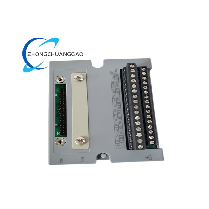
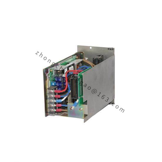
Industrial terminal board with screw or spring clamp connection points according to system version.
DIN rail mounting base and cabinet fixing elements.
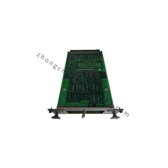
Printed circuit or wired termination layout for analog channels.
Labeling areas for channel identification and loop documentation.
Working Principle
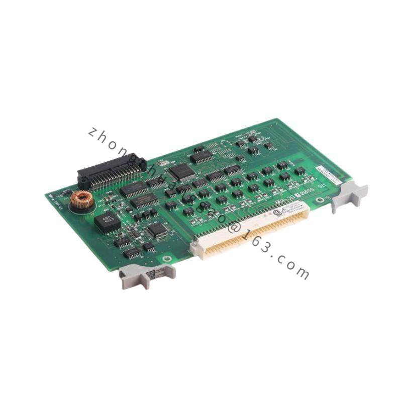
Field analog wires terminate on the board connectors. The board routes signals to the associated Yokogawa analog I/O module or system card. Proper shielding, grounding, and separation maintain signal integrity. Redundant versions provide alternate termination paths according to the system redundancy design.
Installation Requirements
Mount on the specified DIN rail inside a controlled instrument cabinet.
Use shielded cables with proper ground termination at the designated end.
Match the terminal board version to the connected analog I/O module.
Separate signal wiring from high voltage and high current circuits.
Confirm channel assignment and labeling before system commissioning.
Usage Precautions
The 05 basic version is not configured for explosion protected installation.
Verify voltage and signal ranges with the connected I/O module before wiring.
Prevent moisture, corrosive atmosphere, and excessive dust in the cabinet.
Inspect terminal torque and cable insulation during periodic maintenance.
Do not substitute unrelated A1BA4D suffixes without confirming redundancy and channel requirements.