Technical Specifications
Current rating is 8 A continuous and 16 A peak per configured axis or power section. Axis configuration in available datasheets includes a three-axis power-circuit board variant and, in other service references, a single-axis 8/16 A feed power board paired with separate regulation electronics. System supply context for SIMODRIVE 610 is 380 V to 480 V three-phase AC with overall feed-drive power ranges around 1.5 kW to 22 kW depending on axis count and motor sizing. Control interface is analog speed or current command with resolver/encoder feedback handled by the regulation board. Cooling is forced-air convection through the drive chassis fan. Insulation and protection are industrial power-electronic grade. Obsolete status applies; Siemens discontinued SIMODRIVE 610 support dates in legacy product notices.
Functional Features
The power circuit provides three-phase inverter output, current sensing, overcurrent hardware shutdown, short-circuit protection and cooperation with the regulation board for speed-loop and current-loop control. Modular plug-in construction enables replacement of the power section without replacing the entire drive chassis. Hardware fault signaling is generated when current limits or bridge faults are detected.
Application Scenarios
Legacy CNC machining centers, turning machines, milling machines, grinding machines and retrofit spare-part programs using SIMODRIVE 610 with SINUMERIK 3, 810, 820 or comparable analog CNC platforms. Suitable for maintenance inventories where original 8/16 A feed power stages must be exchanged.
Performance Parameters
Output current capacity is 8 A continuous and 16 A peak per axis/section. PWM switching produces adjustable three-phase voltage and frequency for AC feed servo motors. Current feedback resolution and loop response are determined by the paired regulation board and motor transducer. Overcurrent protection acts at hardware level to disconnect gate drive and report a power-stage fault.
Material Composition
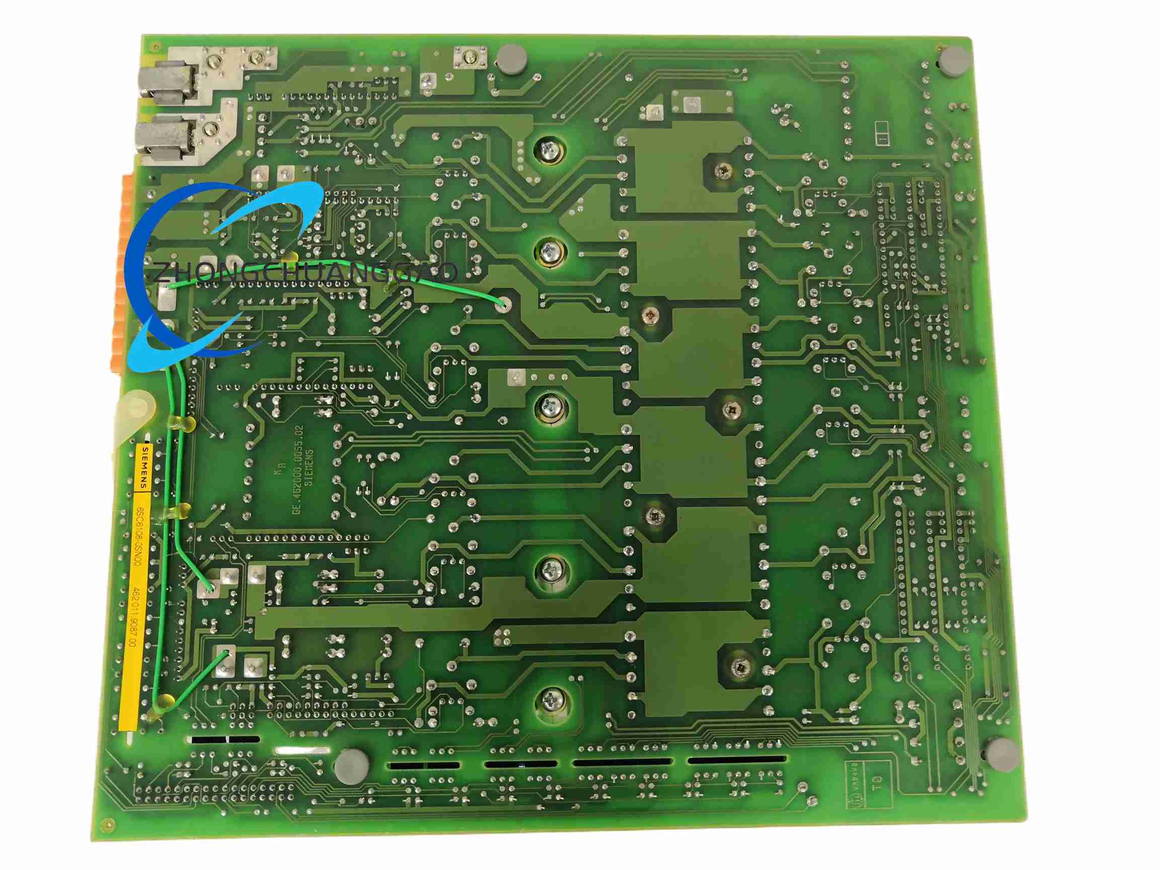
Substrate is industrial high-current FR-4 printed circuit board. Main power components include IGBT or transistor modules, rectifier/precharge stages according to chassis design, gate drivers, current-shunt or Hall sensors, DC-bus terminals and snubber components. Mechanical parts include metal fixing brackets, heat sink plates, insulated hardware and edge or back-plane connectors.
Structural Characteristics
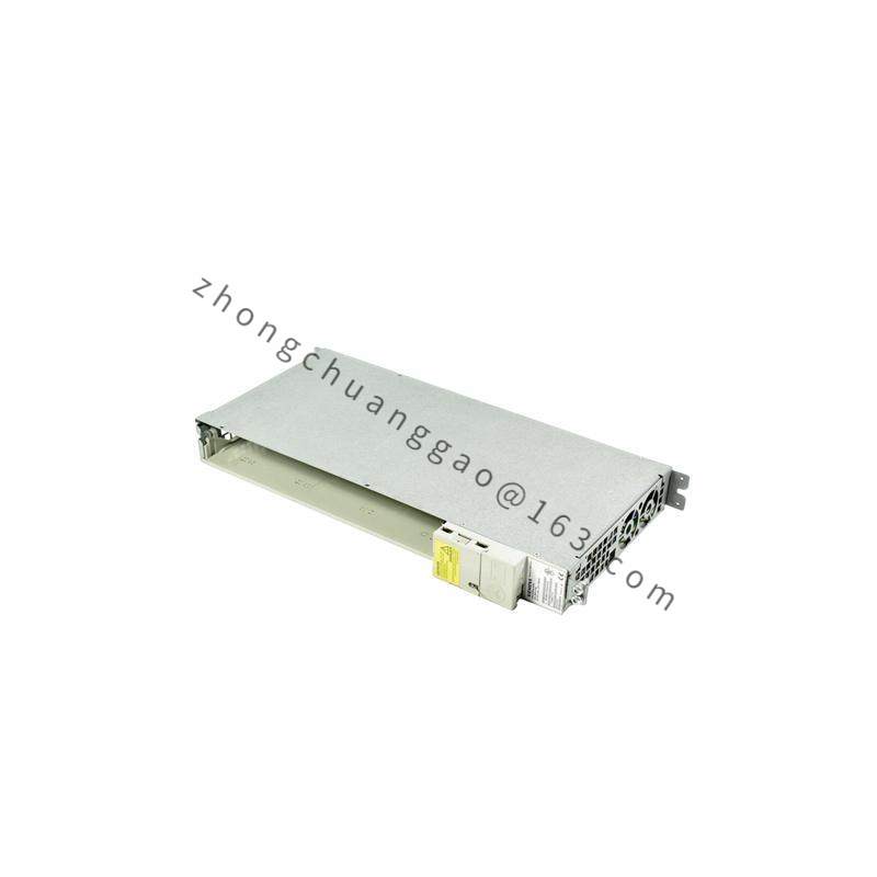
Plug-in power-board format for insertion into the SIMODRIVE 610 rack or drive chassis. Edge or back-plane connector carries control signals and DC-bus power. Front or board-edge terminals provide motor-phase output wiring according to the specific single-axis or multi-axis variant. Heat sinks are mounted directly on power semiconductors. The module works together with a separate regulation/control board that stores drive parameters.
Working Principle
DC-bus voltage from the SIMODRIVE 610 supply module is delivered to the power board. The control/regulation board sends analog set-point and enable signals. Power semiconductors switch the DC bus into three-phase PWM output for the servo motor. Current sensors return motor current to the regulation electronics for closed-loop speed and torque control. On overcurrent, short-circuit or hardware fault, the protection circuit removes gate drive and raises a fault signal to the CNC drive diagnostics.
Installation Requirements
Install only in the matching SIMODRIVE 610 chassis with compatible regulation board, supply module and motor rating. Confirm 8/16 A rating, axis count and connector layout before insertion. Verify DC-bus voltage, control voltage and enable wiring according to the SIMODRIVE 610 manual. Ensure chassis fan operation and cabinet airflow for forced cooling. Connect motor phases in the exact sequence defined by the wiring diagram. Complete protective-earth bonding for the drive cabinet and power section.
Usage Precautions
Treat the module as high-voltage power electronics; only qualified personnel may handle, insert or test it. Check back-plane engagement and torque on power terminals before energizing. Do not operate without forced-air cooling or with a faulty chassis fan. Match the regulation board firmware/parameter set to the replaced power stage. Because SIMODRIVE 610 is obsolete, use tested spare or refurbished units, verify insulation resistance before commissioning, and dispose of electronic waste according to local WEEE and hazardous-material rules.