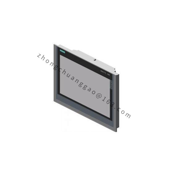
Technical Specifications
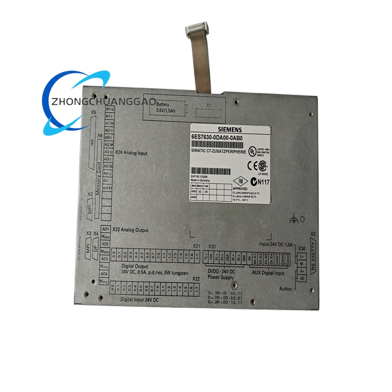
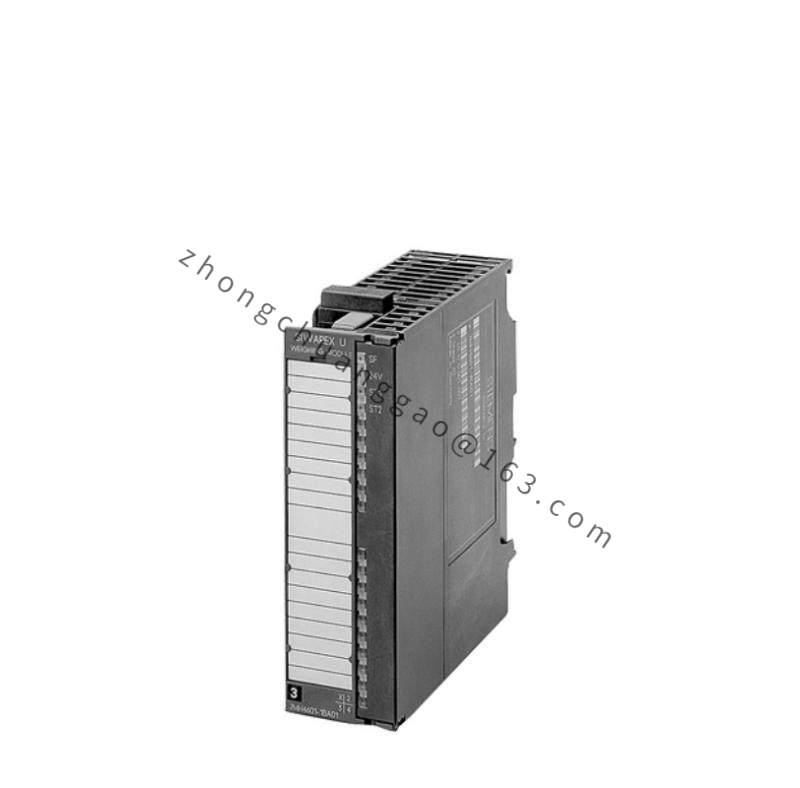
Digital inputs are 16 channels. Digital outputs are 16 channels. Analog inputs are 4 channels. Analog outputs are 4 channels. Universal inputs are 4 channels. Rated supply voltage is 24 V DC. Permissible supply range is 20.4 V DC to 28.8 V DC. Typical no-load current is approximately 350 mA. Maximum inrush current is approximately 1.0 A. Typical power loss is approximately 11 W. Body dimensions are 230 mm width, 158 mm height and 56 mm depth. Module weight is approximately 1.35 kg. Compatible controllers include C7-633, C7-634, C7-623/P, C7-624/P, C7-626/P and C7-626/P DP.
Functional Features
The module combines discrete and analog signal processing in one expansion unit. It provides seamless C7 bus integration, fixed channel assignment for digital and analog functions, universal inputs for flexible sensor connection, and industrial-grade signal isolation appropriate for factory environments.
Application Scenarios
Packaging machines, assembly stations, process skids, chemical and pharmaceutical batch control, food and beverage machines, automotive test benches, and compact SCADA front-end panels using C7 controllers.
Performance Parameters
The expansion bus transfers digital states and analog converted values to the C7 CPU in real time. Analog resolution and update rate follow the C7 system configuration. Total I/O load must remain within the controller power budget and process image limits defined by the C7 hardware configuration.
Material Composition
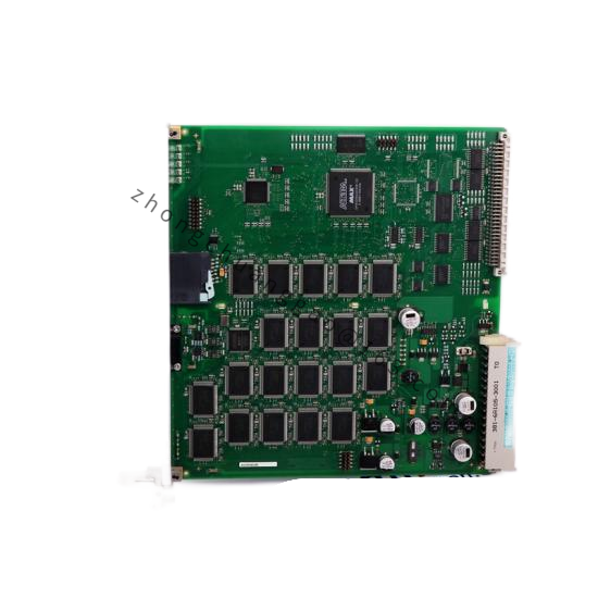
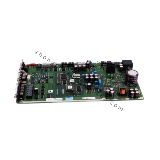
Housing uses reinforced industrial thermoplastic. Internal circuits use FR-4 printed circuit boards with industrial-grade relays, optocouplers, converters and terminal connectors. Contact elements use nickel- or gold-plated alloys according to channel type.
Structural Characteristics
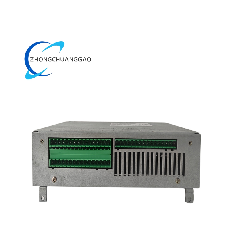
The unit has a compact rectangular body with front or side wiring according to the C7 mounting arrangement. Channel groups are laid out for clear separation of digital input, digital output, analog input, analog output and universal input wiring. Bus connection is made through the C7 expansion interface.
Working Principle
External sensors and actuators connect to the module terminals. Digital inputs are conditioned and passed to the C7 CPU as binary states. Analog inputs are converted by internal ADCs and transmitted over the C7 bus. The CPU sends digital and analog output values that the module converts to field voltage, current or contact signals.
Installation Requirements
Mount the module adjacent to or as specified by the compatible C7 controller. Provide a stabilized 24 V DC supply sized for all C7 base and expansion loads. Reserve 230 mm by 158 mm by 56 mm minimum space for the module body and wiring bend radius. Connect only to supported C7-633, C7-634, C7-623/P, C7-624/P, C7-626/P or C7-626/P DP systems.
Usage Precautions
Use only 24 V DC nominal supply. Confirm analog signal types before wiring universal inputs. Calculate total expansion current so the C7 power budget is not exceeded. Apply ESD protection during handling. Verify channel addressing in the C7 hardware configuration before commissioning.