Technical Specifications
Rated supply voltage is 24 V DC. Permissible static voltage range is 20.4 V DC to 28.8 V DC. Dynamic voltage range is 18.5 V DC to 30.2 V DC. Rated operating current is 450 mA. Inrush current is 0.9 A at 24 V DC. Power consumption is 12 W with fans running and 1.4 W without fans. Installed fuse is 5 x 20 mm, 1.0 A slow-blow. Relay signal contacts support 24 V DC with maximum 200 mA per contact. Spring terminal wire size is 0.5 mm² to 2.5 mm². Dimensions are 482.5 mm width, 109.5 mm height and 235 mm depth. Net weight is approximately 1.6 kg. Fan service life is approximately 70,000 hours at 40 °C ambient temperature.
Functional Features
The unit delivers continuous rack ventilation, automatic fan start, speed monitoring, LED status indication, relay fault output and integrated electronic monitoring. After power-up, fans require about 10 seconds to reach commanded speed before fault signaling stabilizes. The design keeps modules running during a single fan defect and reports the fault instead of immediately shutting down ventilation.
Application Scenarios
S7-400 PLC control cabinets, high-density I/O racks, process automation racks, power and utility control rooms, metallurgy and water-treatment automation systems, and retrofit spares for existing S7-400 installations.
Performance Parameters
Airflow is engineered for S7-400 rack heat loads. Fan speed feedback is processed by the monitoring circuit. Fault relay and LED states provide real-time status to CPU diagnostics or cabinet alarm systems. Startup stabilization time is 10 seconds before normal fault signaling.
Material Composition
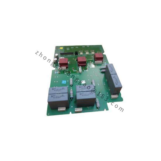
Enclosure uses industrial sheet-metal and coated framework. Fans use engineered thermoplastic blades and sealed bearings. Monitoring circuit uses FR-4 printed circuit board with surface-mount electronics. Spring terminals use tinned copper alloy.
Structural Characteristics
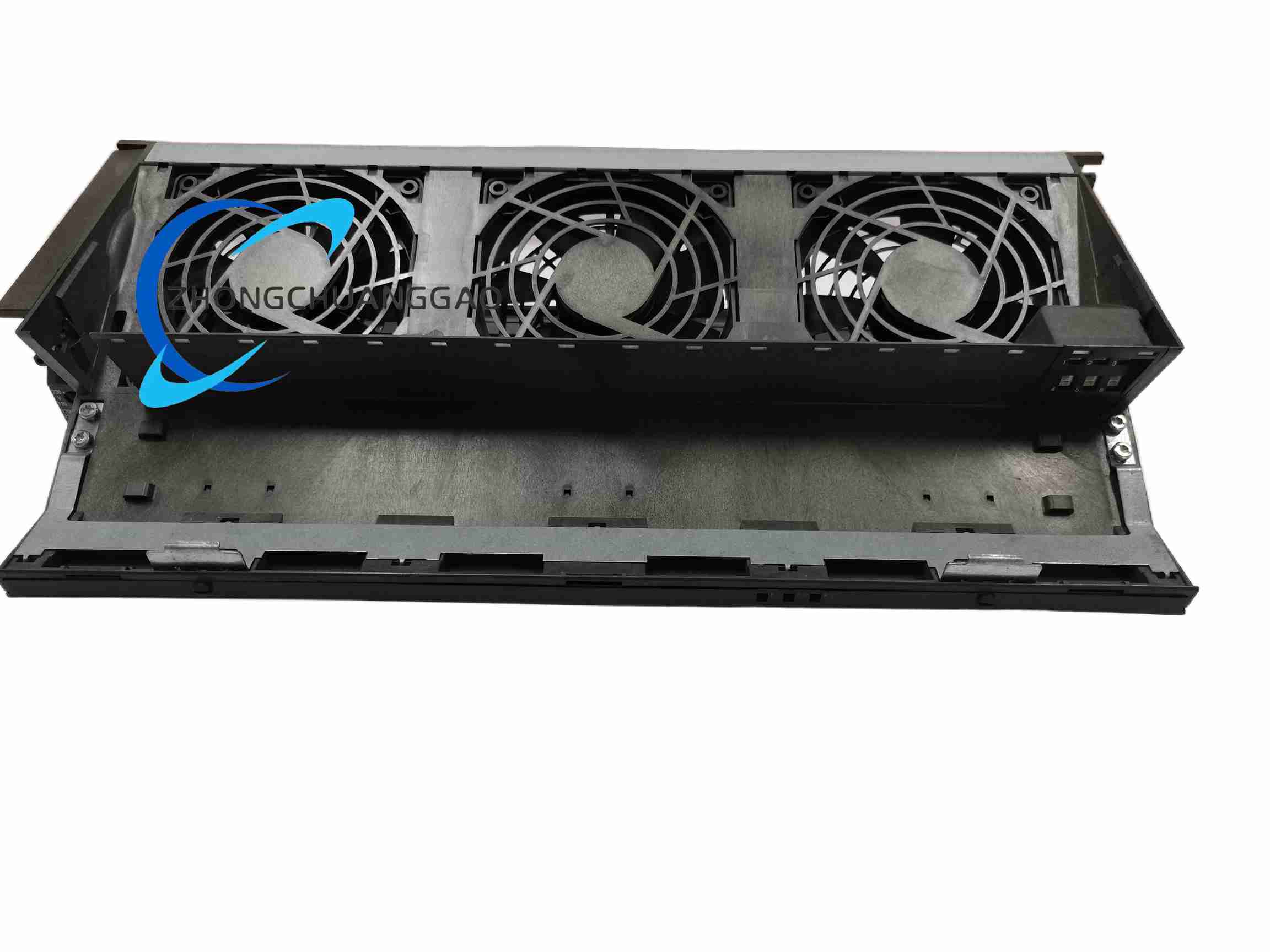
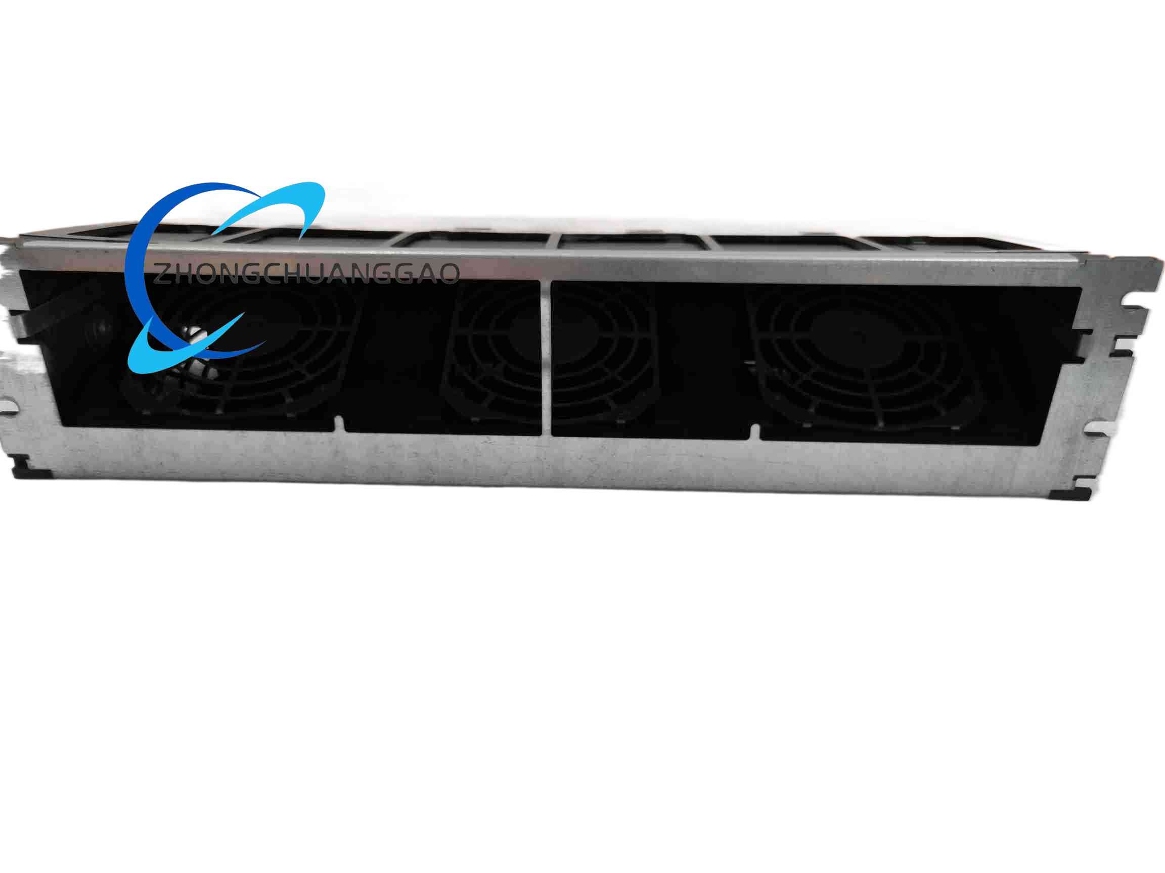
The subassembly mounts in the designated S7-400 fan position or rack accessory space. Front provides LED indicators and access to monitoring elements. Bottom or side provides spring power terminals. Internal guide accepts the monitoring PCB. The profile matches S7-400 rack width for uniform cabinet layout.
Working Principle
24 V DC power drives multiple axial fans. The monitoring circuit measures rotational speed and compares it with set thresholds. If a fan stalls or slows below specification, the circuit changes LED status and activates the fault relay. The S7-400 system or external alarm panel receives the contact state for logging and maintenance action.
Installation Requirements
Install only in compatible S7-400 racks or fan subassembly positions. Connect L+ and L− with correct polarity to 24 V DC supply. Use 0.5 mm² to 2.5 mm² stranded wire with ferrules. Mount the rack in a cabinet with adequate front and rear ventilation clearance. Connect the fault relay to the plant alarm system when centralized monitoring is required. Ensure the monitoring PCB is fully seated in its guide before energizing.
Usage Precautions
Verify 24 V DC polarity before connection. Replace the fuse only with 5 x 20 mm 1.0 A slow-blow type. Insert the monitoring PCB in the correct orientation. Keep cabinet ambient temperature within the S7-400 rack specification, normally 0 °C to 60 °C. Allow 10 seconds after power-up before clearing fan alarms. Perform maintenance with qualified personnel and observe ESD handling rules.