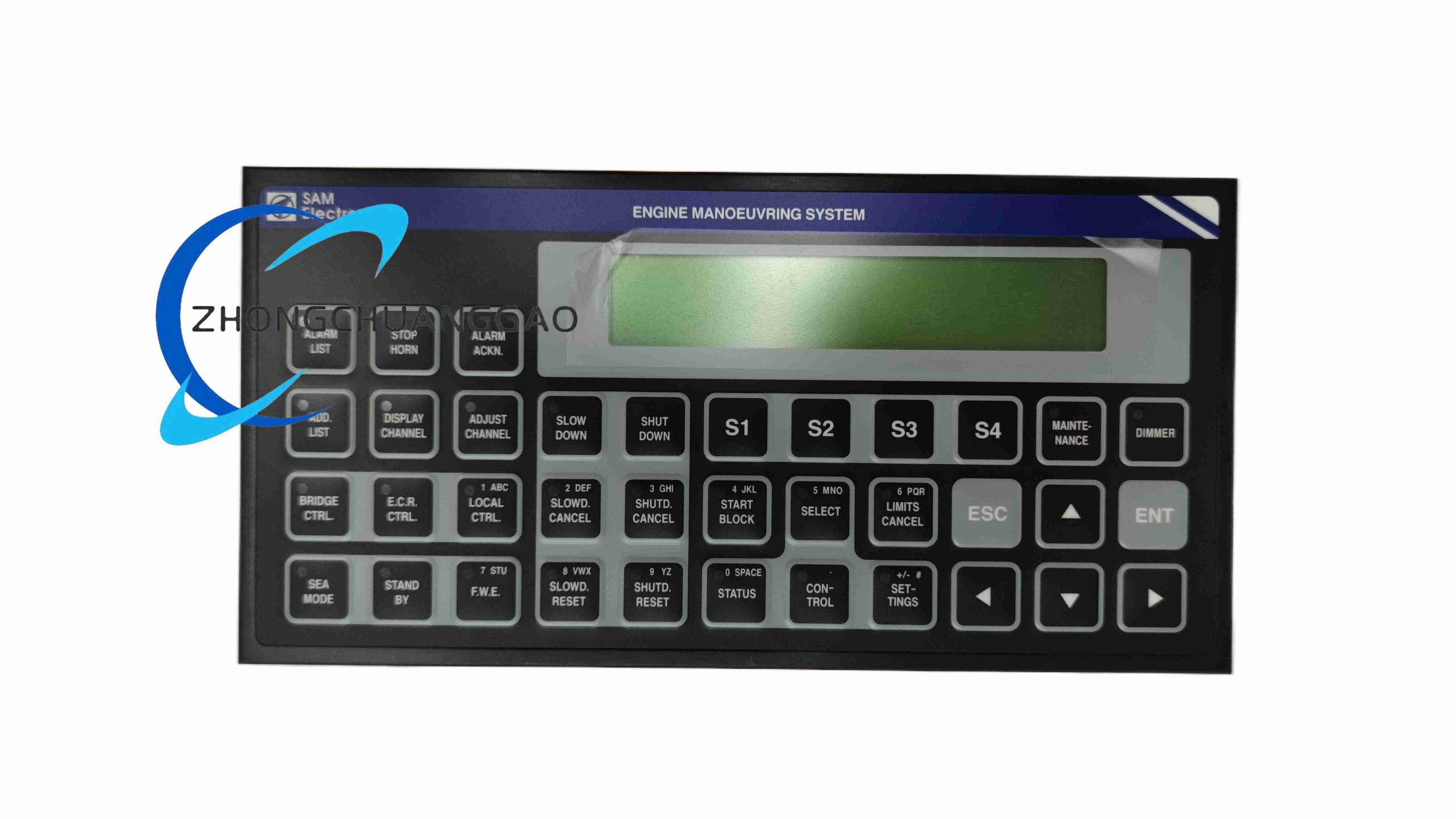
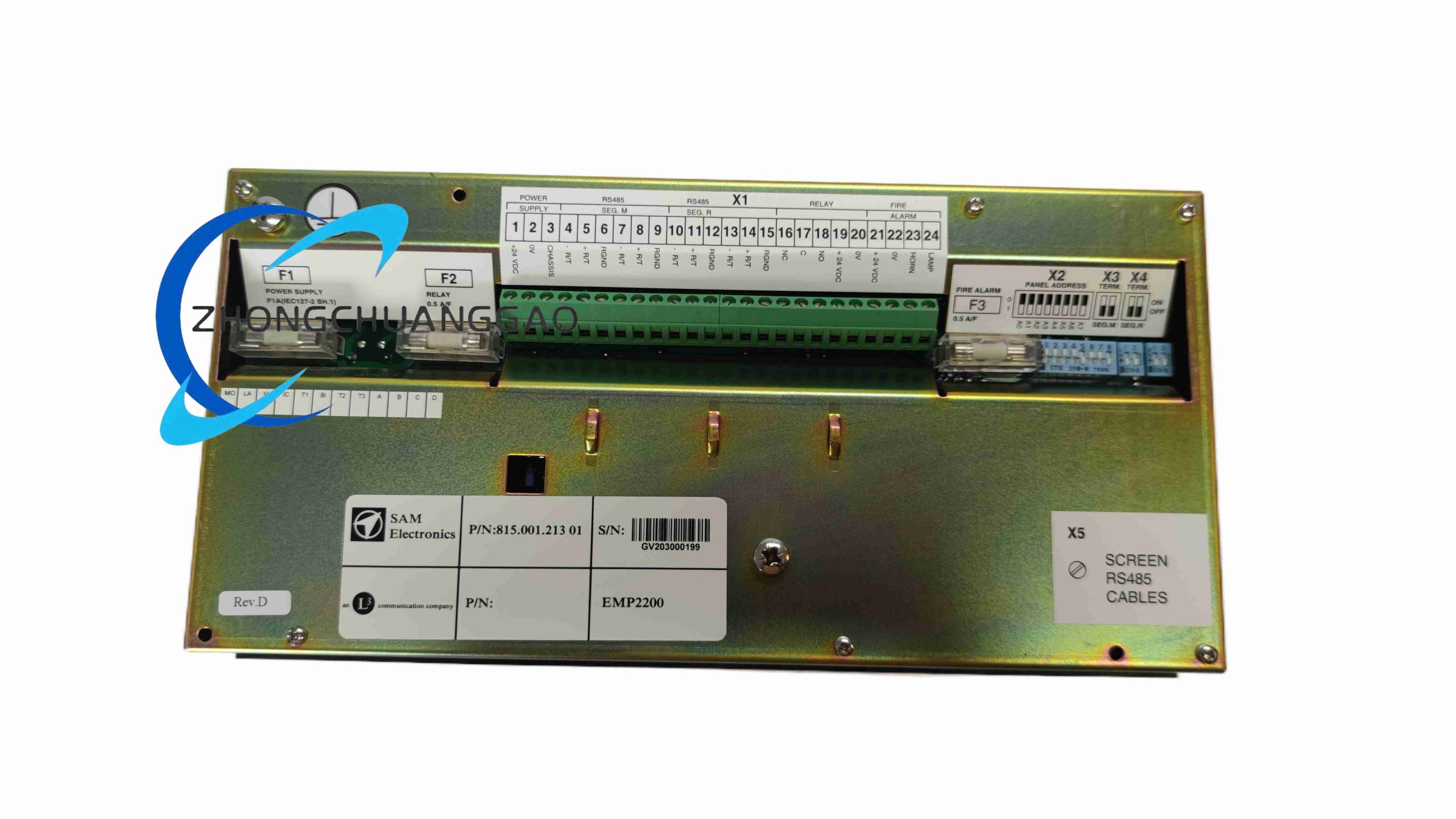
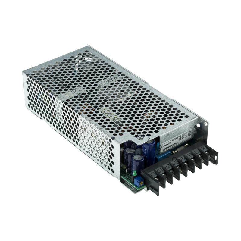
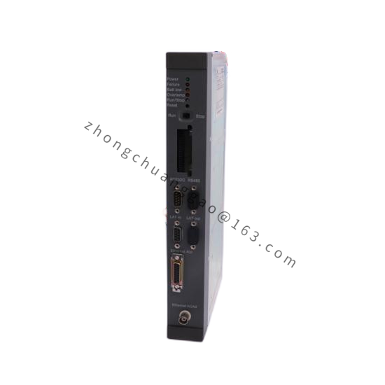
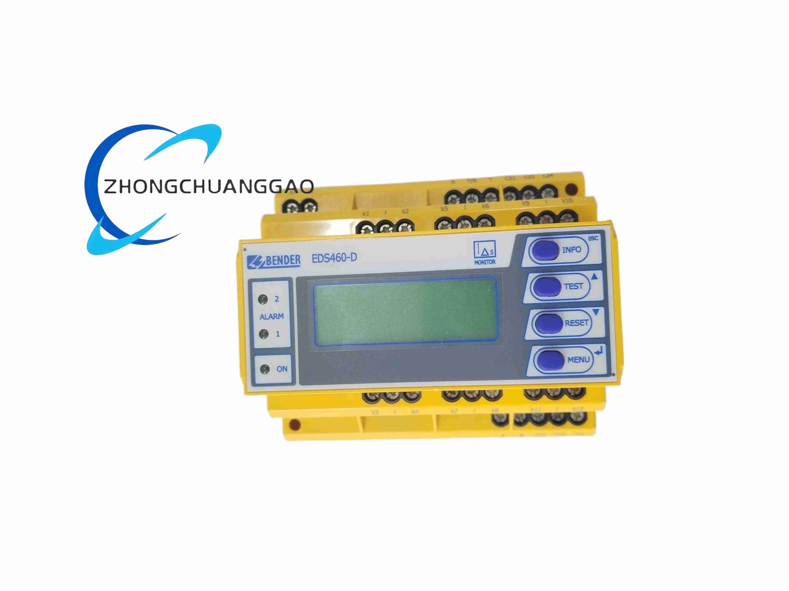
Technical Specifications
Supply: 24 VDC nominal, 18–32 VDC range
Power consumption: max 45 W
Digital inputs: 128 galvanically isolated binary alarm inputs
Relay outputs: 64 SPST, 5 A / 250 VAC
Communication: dual redundant CAN bus, RS485 Modbus RTU, Ethernet TCP/IP
Operating temperature: -20 to +60 °C
Storage temperature: -40 to +70 °C
Protection: IP30 front panel, IP20 internal
Compliance: IEC 60945, DNV, ABS, LR marine standards
Performance Parameters
Input scan cycle: 10 ms
Alarm transmission delay: ≤ 20 ms
Event log capacity: 10,000 events
Data retention: ≥ 10 years non-volatile
Relay life: 10,000,000 switching cycles
Vibration: 2–100 Hz, 1 mm amplitude
Material Composition
Front panel: 3 mm cold-rolled aluminum alloy with anti-corrosion coating
Chassis: galvanized steel sheet metal
PCB: FR4 high-temperature flame-retardant
Terminals: glass-fiber reinforced PA66 with tin-plated copper contacts
Structural Characteristics
19-inch rack mount
6U height
Modular pluggable I/O cards
Separated power, signal and communication compartments
Working Principle
Continuously polls isolated binary sensor inputs, filters noise, timestamps valid alarms, stores events in flash memory, activates relay outputs and broadcasts status over redundant CAN/Ethernet buses.
Application Scenarios
Cargo ships and container ships
Tankers and bulk carriers
Passenger ferries
Naval auxiliary vessels
Offshore support vessels
FPSO units
Installation Requirements
Install in climate-controlled machinery room cabinet
Ambient humidity ≤ 90% non-condensing
Maintain 50 mm clearance above and below
Separate signal and relay wiring by at least 10 cm
Use filtered marine 24 VDC supply with surge protection
Earth chassis with 4 mm² copper ground cable
Usage Precautions
Do not operate outside -20 to +60 °C
Avoid salt spray and unventilated humidity
Disconnect power before removing I/O modules
Do not exceed 16 units on one CAN bus segment
Calibrate I/O channels every 12 months per marine regulations