Technical Specifications
AC input: 380 to 480 V three-phase, 50/60 Hz
Low-power class option: 200 to 240 V class
DC-bus nominal voltage: 700 V
Rated current examples: 40 A for DKCXX.3-040-7-FW, 100 A for DKCXX.3-100-7-FW
Maximum output voltage: 800 V
Maximum output frequency: 1000 Hz
Control voltage: 24 VDC, 26 W control input power
Brake output: 2 A maximum, 40 VDC maximum
Soft-start resistor: 24 ohm in 100 A example configuration
Overvoltage withstand: 45 V for 1 ms
Continuous power dissipation: 420 W in 100 A example
Peak energy dissipation: 31 kWs in 100 A example
Short-circuit current rating: 42000 A RMS in 100 A example
Protection rating: IP20
Communication: Profibus and modular fieldbus options
Operating temperature: 0 to 45 C nominal, 55 C reduced-performance limit
Altitude: 1000 m without derating in specified versions
Functional Features
Field-oriented vector control for torque, speed and position
Selectable rotary field direction
Soft-start inrush limitation
Integrated brake control output
Profibus and optional modular communication interfaces
Diagnostics through front indicators and controller software
Unified parameter structure across DKC power sizes
Application Scenarios
CNC machine tools
Industrial robots and handling systems
Packaging, printing and converting machines
Material forming and press automation
Servo-controlled test rigs and production lines
Performance Parameters
700 V DC bus supports high-response acceleration and braking
40 A and 100 A examples cover mid-range and high-current servo axes
1000 Hz output frequency supports high-speed spindle and servo operation
Overload and short-circuit ratings follow industrial drive safety design
IP20 enclosure requires installation inside a closed control cabinet
Material Composition
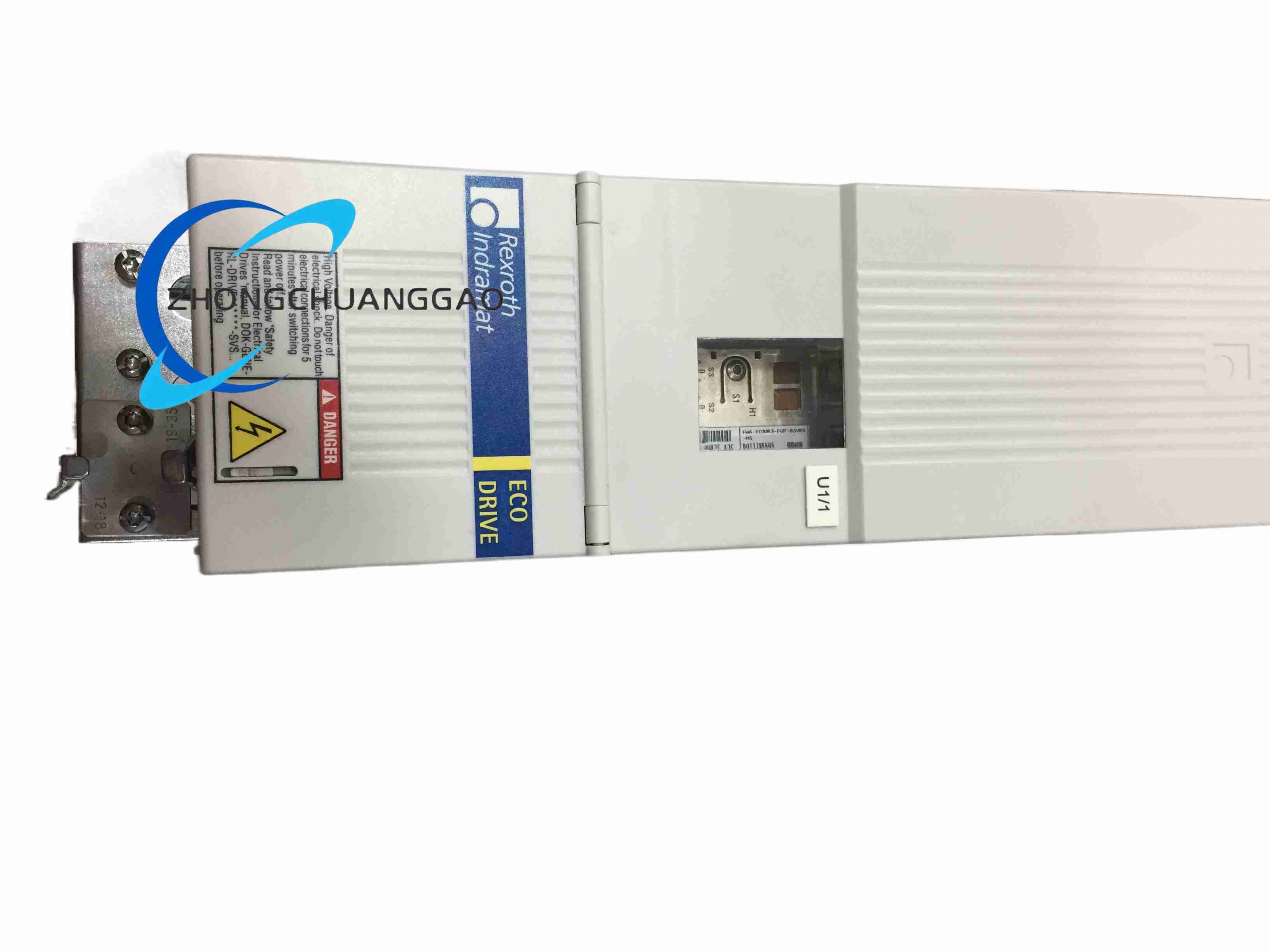
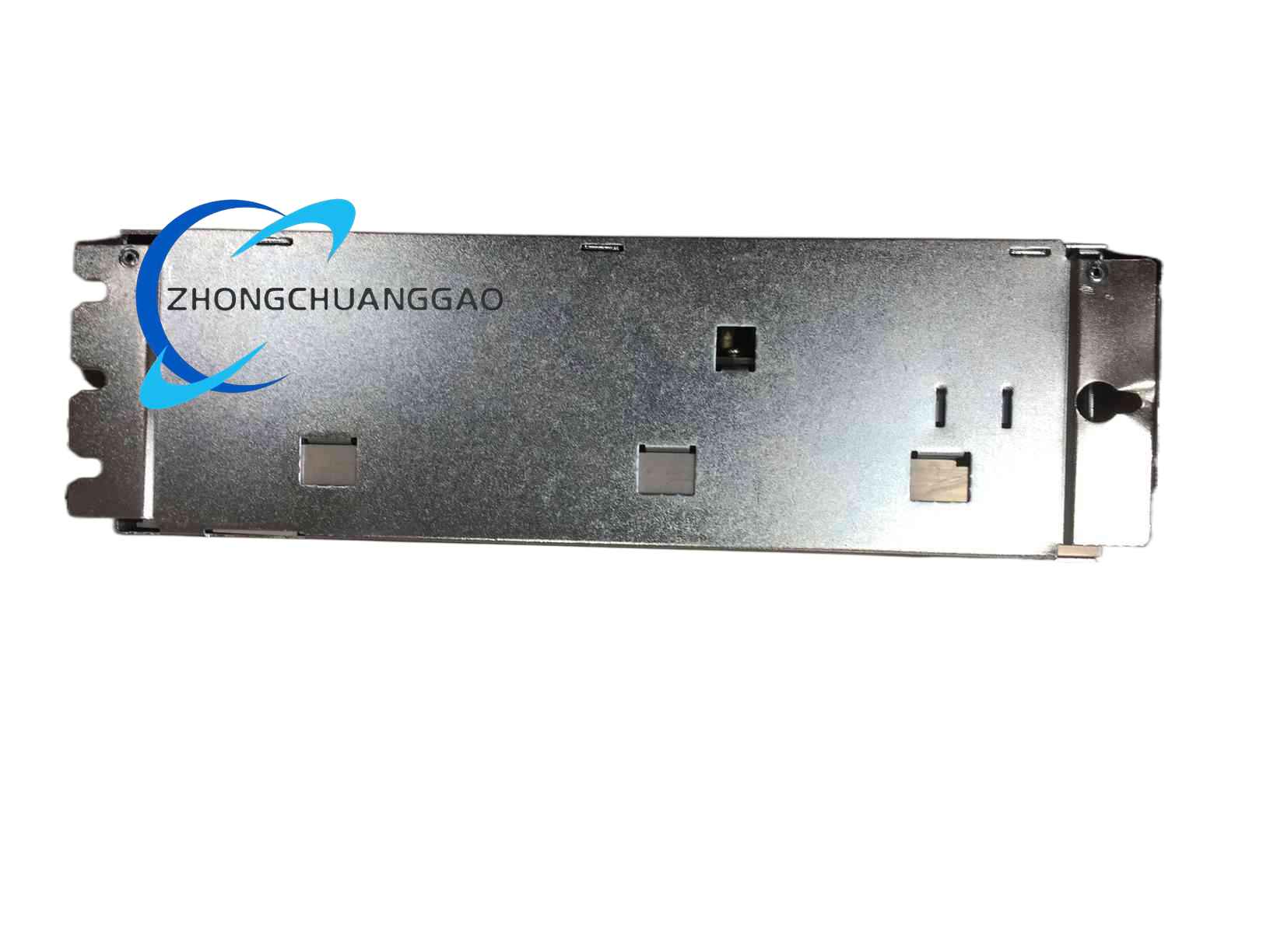
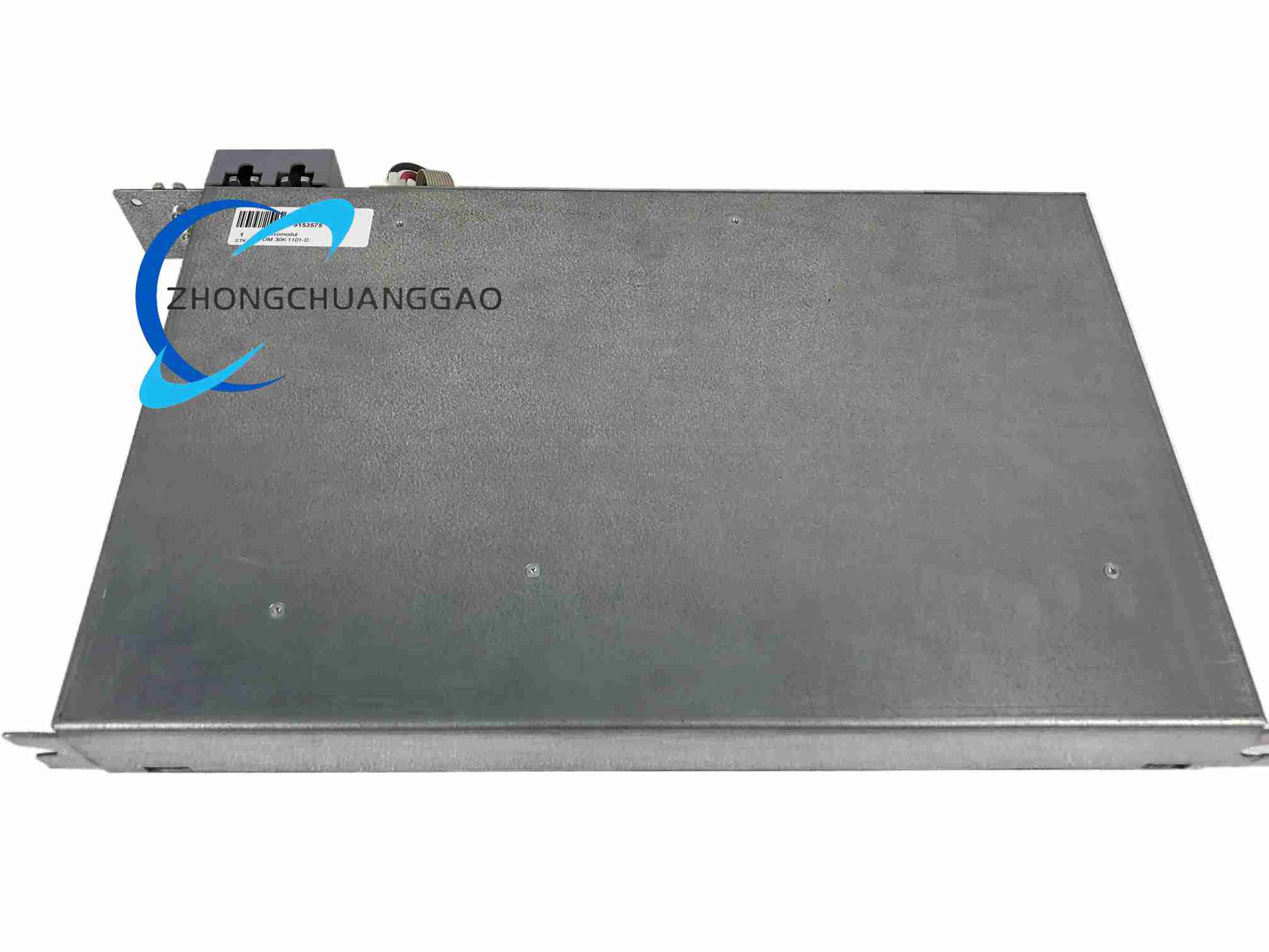
Book-style metal drive enclosure with integrated heat sink surfaces
Internal power section uses insulated power semiconductor modules
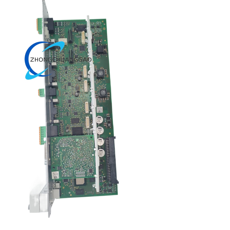
Control section uses multilayer FR4 circuit boards
Bus and signal connectors use plated industrial-grade contacts
Structural Characteristics
Standardized book-format housing for cabinet mounting
Separate power stage and control stage sections
Front status indicators and parameter access interface
Modular communication and option slots depending on suffix
Vertical mounting orientation for convection and blower cooling
Working Principle
The drive rectifies three-phase AC input to a 700 V DC bus. The inverter stage generates PWM voltage output for the servo motor. Feedback from encoder or resolver is processed by the control section for current, speed and position loops. Fieldbus or onboard control commands set motion parameters. The brake circuit and soft-start circuit manage energy during acceleration, deceleration and fault conditions.
Installation Requirements
Install vertically in a grounded control cabinet
Maintain manufacturer-specified clearance around air vents and blower models
Connect 380 to 480 V three-phase supply with proper fusing and isolation
Use shielded motor cables and shielded feedback cables
Ground DC bus, cabinet frame and cable shields to one equipotential point
Configure Profibus or selected fieldbus before initial start-up
Usage Precautions
IP20 protection requires a clean, enclosed cabinet environment
Do not exceed 700 V DC-bus nominal operating limits
Verify firmware compatibility before mixing DKC versions
Use authorized configuration software for commissioning and diagnostics
Ensure brake voltage and current remain within 40 VDC and 2 A
Inspect cooling paths and blower operation on scheduled maintenance