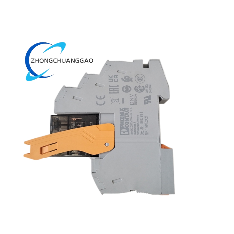
This is a DIN-rail relay module belonging to the RIFLINE complete family. It combines a plug-in electromechanical relay with a push-in base for control-panel and industrial cabinet wiring. The module is built for universal switching duties, signal isolation and load switching in automation, power supply and process systems.
Contact configuration: 2 changeover contacts, DPDT/2 Form C
Contact material: AgNi
Maximum continuous current: 8 A
Maximum switching voltage: 250 VAC / 250 VDC
Minimum switching values: 12 V, 10 mA
Response time: 9 ms
Release time: 10 ms
Coil protection: integrated freewheeling diode
Status indication: yellow LED
Test voltage coil/contacts: 4 kVrms for 1 minute
Test voltage between contact groups: 2.5 kVrms for 1 minute
Rated insulation voltage: 250 VAC
Rated surge voltage: 6 kV input/output
Mechanical service life: 5,000,000 operations
Overvoltage category: III
Pollution degree: 2
Mounting: RIF base / DIN rail with push-in connection
Weight per piece: approximately 65 g
Functional Features
Two independently switched changeover paths allow signal doubling, polarity change and load separation. The freewheeling diode suppresses inductive coil spikes. The LED provides coil-energized status. Push-in termination reduces wiring time and maintains vibration-resistant contact.
Material Composition
Housing is molded thermoplastic rated for industrial enclosure use. Contacts use silver-nickel alloy for arc resistance and low contact resistance. Conductive tracks and terminals use copper alloy with tin plating.
Structural Characteristics
The module contains a relay insert, a base adapter, coil terminal block and status LED. The relay element is removable for replacement while the base remains wired. Input and output sides are physically separated for safe isolation.
Working Principle
Applying 24 VDC to the coil terminals creates a magnetic field that moves the armature. The armature changes both changeover contacts from normally closed to normally open. Removing coil voltage returns contacts by spring force. The freewheeling diode absorbs reverse coil energy during turn-off.
Installation Requirements
Mount the base on a standardized DIN rail. Insert the relay element until locked. Connect A1/A2 coil terminals with correct DC polarity. Verify load current below 8 A per contact and total load within relay rating. Maintain clearance for heat dissipation and label wiring according to control drawings.
Usage Notes
Do not exceed 250 V or 8 A per contact. Use appropriate overcurrent protection on the switched circuit. Check LED status during commissioning. Replace the relay insert if switching delays, welding or intermittent operation occurs. Keep coil voltage within 19.2 VDC to 30 VDC.