Technical Specifications
Axes: one or two axes standard; additional encoder axes with option daughterboards.
Bus options: PC/AT ISA bus or standalone RS-232 operation.
Servo output: on-board D/A analog command; second-axis D/A with AAO option.
Encoder inputs: main encoder per axis; auxiliary encoder support on ACR1000/16 and option boards.
Analog input options: 12-bit auxiliary analog input channels according to AAO/AI option.
PLC I/O: on-board PLC inputs and outputs according to build configuration.
Serial port: RS-232, default 38400, N, 8, 1; auto-baud on supported configurations.
Watchdog: relay output for safety shutdown.
User relay: programmable contact output.
Battery backup: program and parameter retention battery.
Program memory: firmware-dependent; ACR1000/12 and ACR1000/16 builds with ordered program/data memory.
Jumpers: baud-rate, card address, ISA/serial mode selection.
Functional Features
Point-to-point moves, velocity moves, and programmed sequencing.
Linear interpolation and contouring with auxiliary encoder option.
Built-in PLC logic concurrent with motion programs.
Home, limit, and index processing through encoder and flag inputs.
Watchdog relay disconnect for amplifier-enable or machine safety circuits.
Battery-backed program storage for standalone operation.
RS-232 host command interface using Acroloop ASCII/binary command set.
Application Scenarios
Laboratory motion subsystems.
Retrofit CNC and two-axis machining tables.
Packaging and dispensing stations.
Inspection fixtures requiring coordinated X-Y motion.
Standalone servo/stepper demonstrations and OEM machines.
Performance Parameters
Servo update and trajectory timing depend on ACR1000/12 or ACR1000/16 firmware build.
Two-axis coordinated moves supported with main and auxiliary encoder feedback.
Up to four encoder position registers supported on ACR1000/16 with encoder daughterboards.
Serial communication default 38400 baud, 8 data bits, no parity, 1 stop bit.
Watchdog response governed by jumper-selected relay configuration and host supervision interval.
Material Composition
Industrial FR4 ISA controller board.
DSP/MCU processing components according to ACR1000 revision.
Electromechanical watchdog and user relays.
Gold or tin-plated ISA edge connector and signal headers.
Opto-isolated PLC I/O components where fitted.
Structural Characteristics
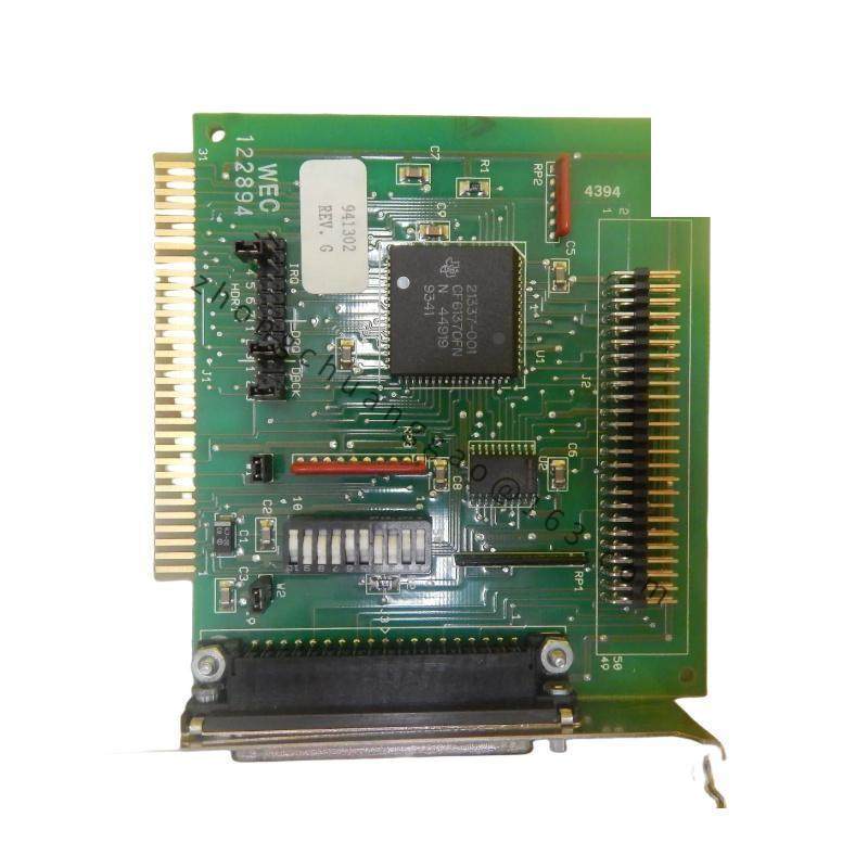
PC/AT ISA card format with edge connector and external header ports.
Dedicated encoder connector P1 per axis.
Analog drive connector P2 for D/A output.
User output connector P3, user input connector P4, auxiliary DAC P5, RS-232 P6.
Interpolation/handshake headers for slave-axis and auxiliary encoder expansion.
Power connector for standalone supply where ISA bus power is not used.
Working Principle
The controller receives motion programs from the host through ISA bus or RS-232. The internal processor calculates trajectory, PID/servo correction, and PLC logic, then outputs analog D/A commands to servo amplifiers. Encoder feedback updates position registers; home, limit, and fault inputs modify motion state. The watchdog relay opens when program execution, communication, or safety supervision fails.
Installation Requirements
Set ISA base address and baud jumpers before inserting the card.
For ISA operation, install in a compliant PC/AT slot and verify BIOS/resource allocation.
For standalone operation, provide the Acroloop-recommended DC supply and RS-232 null-modem cable.
Connect encoders with proper A/B/Z differential or single-ended wiring per port definition.
Install watchdog relay contacts in amplifier-enable or machine-stop circuit.
Usage Precautions
Enable amplifier outputs only after servo tuning and limit verification.
Do not change ISA address jumpers while the host computer is powered.
Backup program and parameter memory before firmware or option changes.
Confirm D/A output load current with the amplifier specification.
Test watchdog relay separately before relying on automatic safety shutdown.