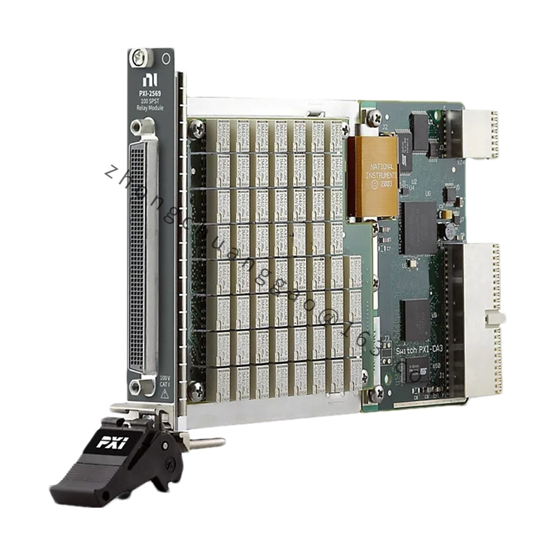
NI CFP-AIO-600
Product Introduction
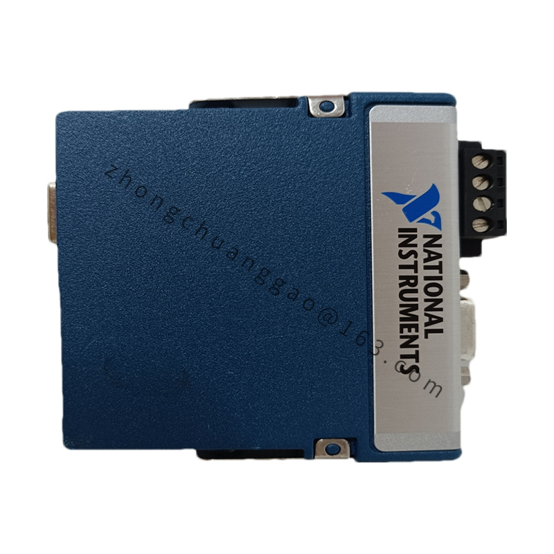
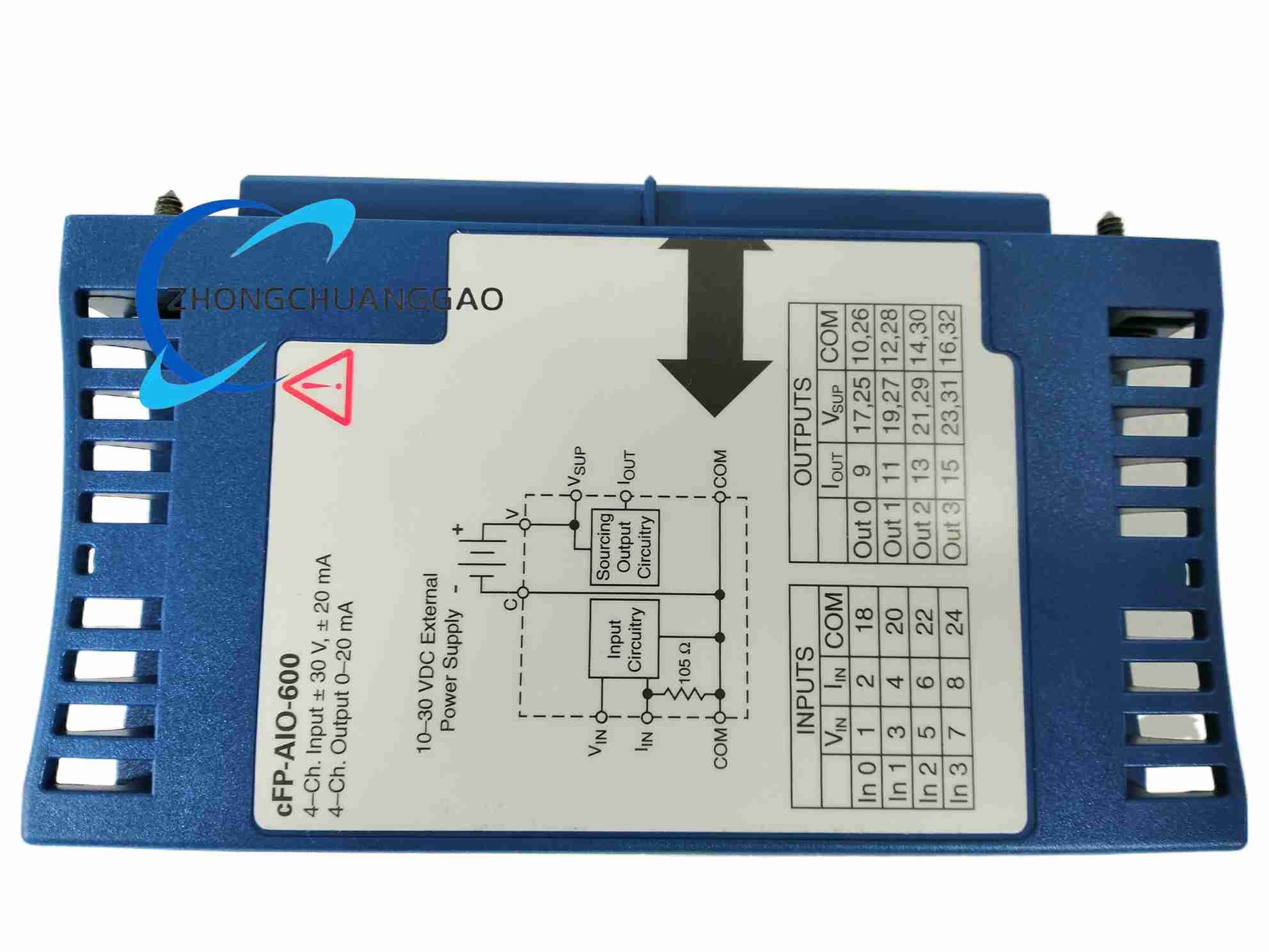
cFP-AIO-600 performs combined analog measurement and analog current output in one Compact FieldPoint module. It acquires voltage or current signals from transmitters, sensors, and field instruments, converts the values for the controller, and generates isolated 4 to 20 mA or 0 to 20 mA output signals for valves, actuators, and loop controllers. The module is intended for distributed I/O, process control, and rugged industrial data-acquisition systems.
Detailed content
Technical Specifications
The module provides four analog input channels and four analog current output channels. Input supports 11 ranges up to ±36 V or ±24 mA with overranging. Output supports 0 to 20 mA and 4 to 20 mA ranges. Resolution is 12 bits for input and output. Hardware update rate is 1.7 kHz. Input accuracy is ±0.07% reading and ±0.08% full scale at 15 to 35°C. Output accuracy is ±0.03% of output at 15 to 35°C. Output external power is 10 to 30 VDC; total output-section current is approximately 125 mA for all four channels. Internal output voltage drop is 3 V. Maximum resistive load is 1 kΩ with 24 V loop supply. Channel-to-ground isolation is 250 Vrms Measurement Category II, verified by 2300 Vrms dielectric withstand for 5 seconds. Channel-to-channel isolation is not provided. Operating temperature is -40 to 70°C. Storage temperature is -55 to 85°C. Relative humidity is 10 to 90% noncondensing.
Function Features
Automatic signal scaling and linearization are performed for engineering-unit exchange with the host software. Onboard diagnostics include open-loop detection on output channels and fault indicators. Current inputs are protected up to ±100 mA or ±10 V. Hot-swappable installation is supported on powered Compact FieldPoint backplanes. The module reads analog inputs, converts them to digital values, and updates current outputs without host-side binary scaling routines.
Application Scenarios
Process-control loops, pressure and flow transmitter interfacing, valve positioning, tank level monitoring, environmental test stands, remote I/O skids, and industrial systems requiring combined analog acquisition and analog control output.
Performance Parameters
Input sampling and output updating operate at a 1.7 kHz hardware rate. Twelve-bit conversion supports fine setpoint and measurement resolution for 4 to 20 mA loops. With 24 V external output power, each output drives up to 1 kΩ; lower supply voltage reduces allowable load resistance because of the 3 V internal drop.
Material Composition
The module uses a conformal-coated industrial printed-circuit assembly, metal or engineered-plastic housing components, isolated power and signal circuitry, and plated connector contacts suitable for control-cabinet service.
Structure Features
cFP-AIO-600 mounts on a Compact FieldPoint backplane cFP-BP-x. Captive screws, alignment keys, and guided seating prevent misinsertion. Screw-terminal or connector-block wiring provides analog input, analog output, loop power, and common connections according to the installed cFP-CB-x connector block.
Working Principle
The input section conditions voltage or current signals, applies programmable range scaling, converts the result with a 12-bit ADC, and transfers digital values to the FieldPoint network module. The output section receives digital setpoints from the network module, converts them through a 12-bit DAC and current-source stage, and drives 0 to 20 mA or 4 to 20 mA into the field loop. External loop power supplies the output transistors; isolation barriers separate channel grounds from the backplane communication bus.
Installation Requirements
Install the module on a compatible Compact FieldPoint backplane inside a sealed enclosure for outdoor or harsh duty. Align captive screws with backplane holes, seat the module firmly, and tighten captive screws to 1.1 N·m using a No. 2 Phillips driver with at least 64 mm shank. Connect external 10 to 30 VDC loop power for the output section. Use shielded analog cable and proper grounding for Measurement Category II isolation.
Usage Notes
Verify input range, output range, and loop supply before energizing. Do not exceed 1 kΩ load per output at 24 V loop supply. Check open-loop indicators after wiring changes. For altitudes above 2000 m, apply derated isolation values from the product safety label. Use only calibrated current loops and confirm short-circuit protection before maintenance.