Technical Specifications
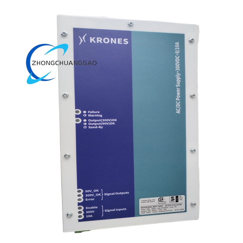
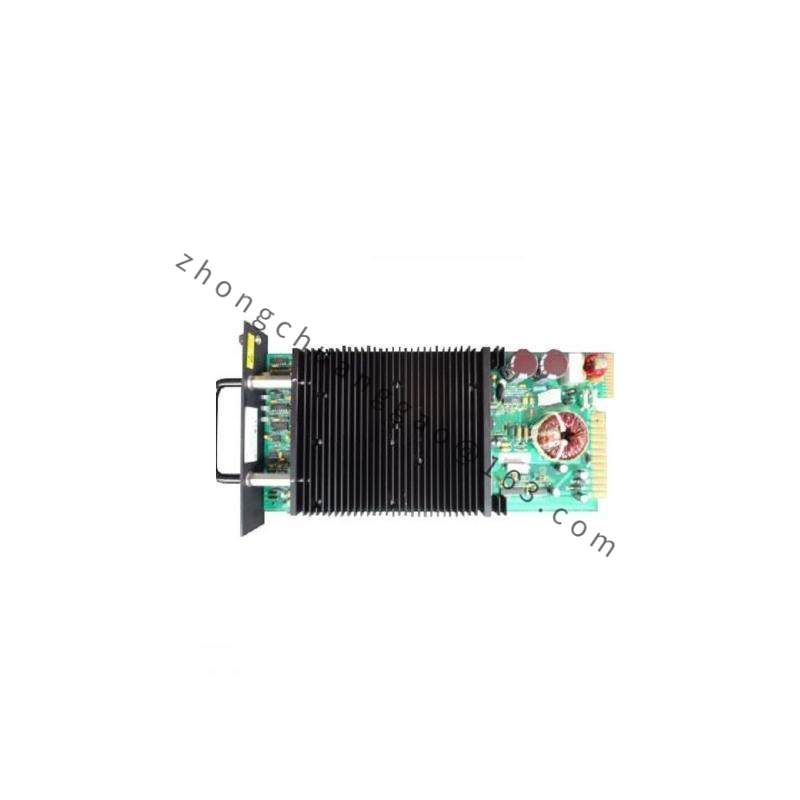
Brake resistor configuration: continuous dissipation 3000 W, nominal 480 V AC three-phase drive matching, 300 s peak thermal rating, forced-air cooling, over-temperature thermal cutout, IP20 metal enclosure. AC/DC power configuration: three-phase AC input 380 to 500 V, frequency 50 to 60 Hz, Krones material number 0.903-78-348-1, industrial DC output conversion for controller and drive auxiliary power.
Functional Features
Brake version provides balanced three-phase resistive load, fan-failure interlock, thermal bistable cutout, modular element stacking and phase-isolated terminals. Power-module version provides AC to DC conversion, stabilized auxiliary voltage, overload protection and industrial cabinet mounting.
Application Scenarios
High-speed bottling lines, beverage filling and capping conveyors, food packaging systems, glass and can handling lines, variable frequency drive regenerative braking, control-cabinet auxiliary power supply.
Performance Parameters
Brake version: 3000 W continuous, 300 s overload capacity, resistor surface peak temperature up to 280°C, forced airflow through vertical element channels. Power version: 380 to 500 V AC input, 50 to 60 Hz, regulated DC output according to Krones drive requirement.
Material Composition
Carbon-steel support frame with anti-rust powder coating, nickel-chromium resistance wire on ceramic insulators, mica thermal barriers, die-cast aluminium fan housing, copper bus bars, high-temperature thermoplastic or epoxy terminal insulation.
Structural Characteristics
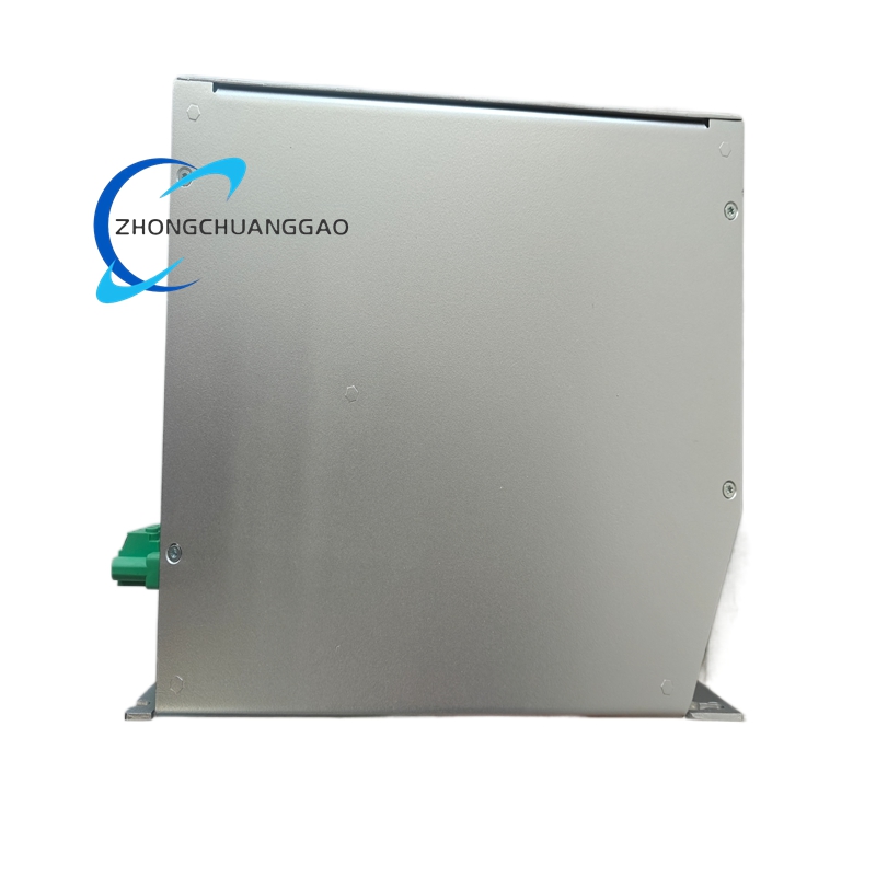
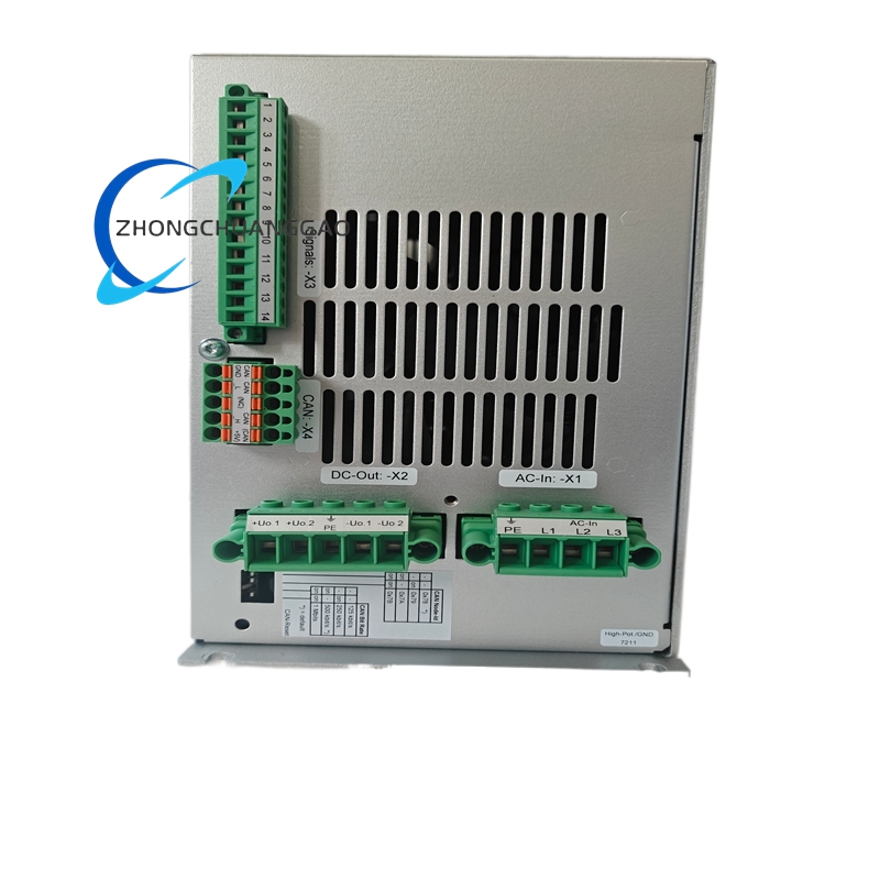
Vertical floor-standing rack frame, perforated front protective grille, horizontally stacked wire-wound elements, bottom axial fan, rear three-phase terminal bus bar, external mounting lugs. Power-module version uses enclosed cabinet-format converter housing with AC input and DC output terminals.
Working Principle
During conveyor deceleration the motor acts as a generator and returns energy to the VFD DC bus. The resistor bank converts this energy into heat through nickel-chromium elements while the fan removes thermal energy. The thermal switch disables drive enable if temperature exceeds the safety limit. The power-module version rectifies and conditions three-phase AC input to supply controlled DC auxiliary voltage to controllers and drive electronics.
Installation Requirements
Secure the resistor vertically to a reinforced floor using four base lugs. Maintain at least 50 cm clearance above the exhaust grille. Connect rear bus bars with torque values specified by Krones, commonly around 8 N·m for high-current terminals. Integrate thermal cutout and fan-fault contacts in series with VFD safety enable. For the power module, mount in a ventilated cabinet, connect 380 to 500 V AC input through protected feeders and ground the chassis.
Usage Precautions
Never block fan intake or exhaust openings. Inspect thermal-switch continuity during planned downtime. Clean dust from resistor elements with dry compressed air every quarter. Keep flammable packaging material at least 1.5 m away. Replace the cooling fan immediately if vibration or airflow loss occurs. For the power module, verify input voltage range before energizing and do not exceed 500 V AC.