

Digital guide
You are here:
- Home
- Kollmorgen
- Kollmorgen S31061-EI
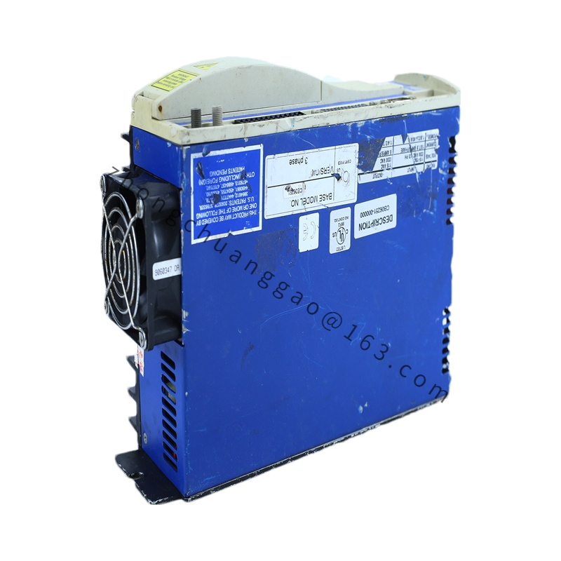
Kollmorgen S31061-EI
Product Overview
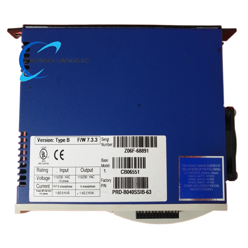
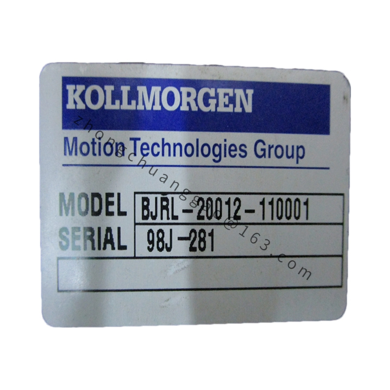
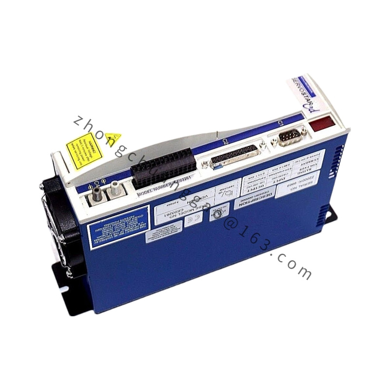
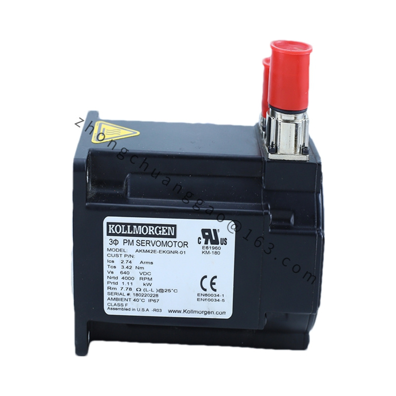
S31061-EI is a single-axis compact digital servo drive from Kollmorgen S300 platform; model breakdown: S310 = 10Arms continuous output current rating; 61 = 110–230VAC single/three-phase input hardware variant; suffix EI = incremental encoder feedback dedicated interface configuration without fieldbus expansion slots. Optimized for small-to-medium frame AKM and Goldline B/M series servo motors, utilizing high-speed DSP triple-loop control architecture for miniature precision automation axes.
Detailed content
Technical & Performance Specifications
- Mains Input Voltage: Single/Three Phase 110–230 VAC (±10%), 50/60Hz
- Continuous Output Current: 10 Arms RMS per phase
- Peak Overload Output Current: 20 Arms RMS (5-second sustainable overload)
- Rated Output Power: 2.2kW
- Velocity Loop Maximum Bandwidth: 450Hz
- Current Loop Sampling Frequency: 250kHz
- PWM Switching Frequency: 8kHz fixed
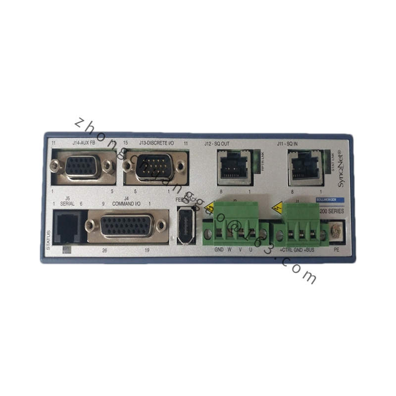
- Standard Communication Interface: RS232 diagnostic configuration port
- Analog I/O Terminals: 2x ±10VDC analog input, 2x ±10VDC analog output
- Digital I/O Terminals: 8x 24VDC sinking/sourcing input, 4x 24VDC output
- Feedback Compatibility (EI Suffix): Incremental sine/cosine encoders, digital square-wave A/B/Z encoders
- Built-In Dynamic Braking Resistor: Integrated internal brake resistor for medium inertia load deceleration
- Complete Protection Suite: Overcurrent, overvoltage, undervoltage, heatsink overtemperature, motor thermal fault, encoder signal loss, output phase short circuit, earth leakage protection
- Cooling Method: Passive extruded aluminum heat sink natural convection cooling
- Protection Class: IP20 cabinet internal installation only
- Net Unit Weight: 2.3 kg
Material Composition
- Unified Chassis Heat Sink: Extruded high-purity aluminum alloy with black anodized anti-static coating
- Main Control PCB: High-density FR4 flame retardant circuit board with tin-free lead plating
- Power Stage Components: Surface-mount three-phase IGBT power bridge module thermally bonded to chassis extrusion
- Terminal Connectors: PA66 flame retardant insulated copper screw terminal blocks
- Internal Dynamic Brake Resistor: Wire-wound high-power ceramic encapsulated resistor assembly
Structural Features
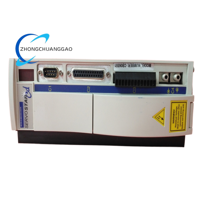
- Slim vertical unified chassis-radiator form factor minimizing cabinet horizontal footprint
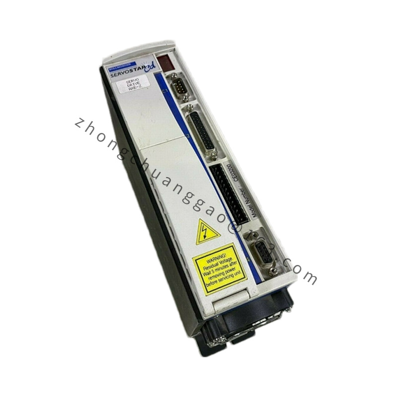
- Front panel physical separation between high-voltage power terminal zone and low-voltage signal terminal zone via internal metal EMI shielding partition
- Dedicated EI-series encoder feedback connector header optimized for incremental encoder wiring harness
- No integrated cooling fan unit; all heat dissipation routed through external chassis extrusion fin array
- Onboard non-volatile flash memory stores complete motor parameter sets for one-click replacement commissioning
Working Principle
Single/three-phase AC mains input rectified to stable DC bus voltage supplying integrated IGBT power inverter stage. High-speed DSP controller samples analog ±10VDC motion command signals and incremental encoder real-time rotor position feedback at 250kHz current loop refresh rate, executing PI Plus PDFF triple-loop control algorithms to eliminate velocity and position tracking deviation. 8kHz SVM PWM modulation generates smooth sinusoidal three-phase excitation current for matched servo motors; integrated wire-wound braking resistor absorbs regenerative energy during rapid load deceleration cycles to stabilize DC bus voltage. Continuous multi-channel fault monitoring circuit samples all critical electrical and thermal operating parameters, triggering instant power stage hardware cut-off upon fault threshold violation.
Function Features
- Ultra-high 250kHz current loop sampling frequency delivers ultra-fast torque dynamic response
- Dedicated EI incremental encoder interface with built-in signal signal conditioning circuit eliminating external amplifier hardware
- Integrated dynamic braking resistor removes requirement for external brake resistor accessory for medium inertia load applications
- Built-in mechanical resonance suppression adaptive filter to eliminate miniature axis oscillation
- Automatic motor identification tuning wizard for zero-manual PID gain setup during commissioning
- RS232 multi-drop serial port supporting synchronized parameter configuration of multiple connected drive units
Advantage Highlights
- Fanless passive cooling design eliminates mechanical fan wear and dust clogging failure modes
- Unified extruded aluminum chassis reduces system component count and assembly wiring complexity
- 450Hz maximum velocity bandwidth enables ultra-fast acceleration/deceleration precision motion cycles
- Dedicated EI incremental encoder interface optimizes signal integrity for optical encoder feedback systems
- CE, UL/cUL, RoHS global safety certification for OEM mass production equipment integration
Applicable Industries
Precision automated assembly equipment, laser marking and engraving machinery, desktop CNC machining centers, medical laboratory automation stages, high-speed packaging labeling equipment, semiconductor micro-assembly workcells
Installation Requirements
- Mandatory vertical cabinet mounting orientation; horizontal installation reduces heat dissipation efficiency by 38%
- Minimum unobstructed airflow clearance: 80mm vertical space above drive top edge, 50mm lateral side clearance
- Mounting metal plate connected to facility star earth grid via ≥6mm² copper protective earth conductor
- Motor power cable specification: ≤20m length use 2.5mm² four-core shielded copper cable
- Incremental encoder feedback cable: Twisted-pair double-shielded 0.25mm² cable with maximum transmission distance 80m
- Strict cable separation rule: Power wiring and signal wiring routed in independent cable ducts; unavoidable crossing implemented at strict 90-degree perpendicular angle only
Operation & Maintenance Precautions
- Cabinet ambient operating temperature limited to 0°C ~ +45°C; temperature above 45°C apply linear 20% continuous output current derate per 10°C temperature rise
- Quarterly compressed dry air cleaning of chassis aluminum extrusion fins to remove accumulated dust blocking heat dissipation airflow
- Disconnect all mains supply and wait minimum 7 minutes for DC bus capacitor full discharge before disassembling terminal wiring
- Do not connect servo motors exceeding 2.2kW rated power output to prevent permanent power module thermal damage
- All incremental encoder wiring connectors must maintain complete double-end shield grounding to eliminate position signal noise drift
- Prohibit deployment within control enclosures containing oil mist, conductive metal dust or acidic corrosive vapor atmospheres
.jpg)