")
Digital guide
You are here:
- Home
- Kollmorgen
- Kollmorgen PRD-0017000L-30
Kollmorgen PRD-0017000L-30
Model Series
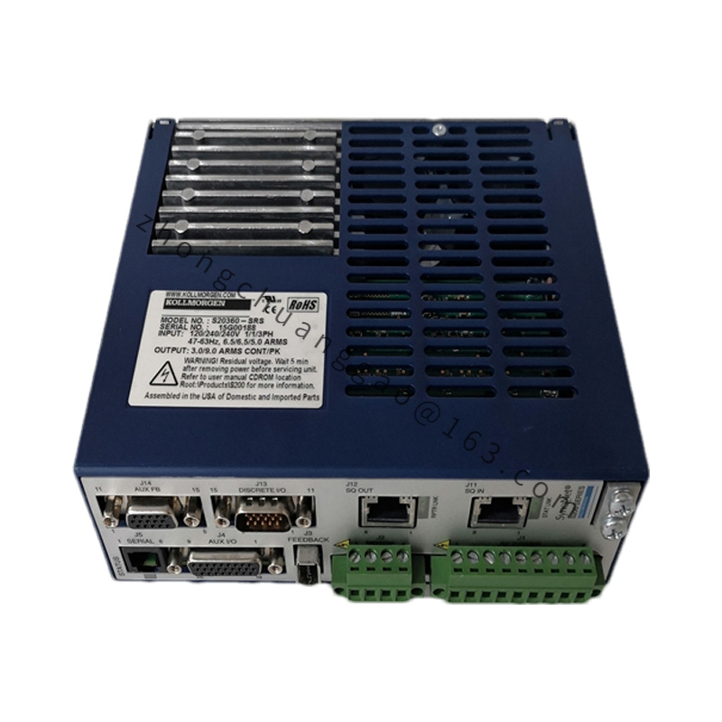
PRD Multi-Axis Shared DC Bus Power Module Family
Product Introduction
Active front-end power supply regeneration module for multi-axis servo systems, converts three-phase AC grid to stable shared DC bus voltage, realizes bidirectional energy flow for regenerative power feedback to grid; eliminates separate braking resistors for multi-drive systems.
Detailed content
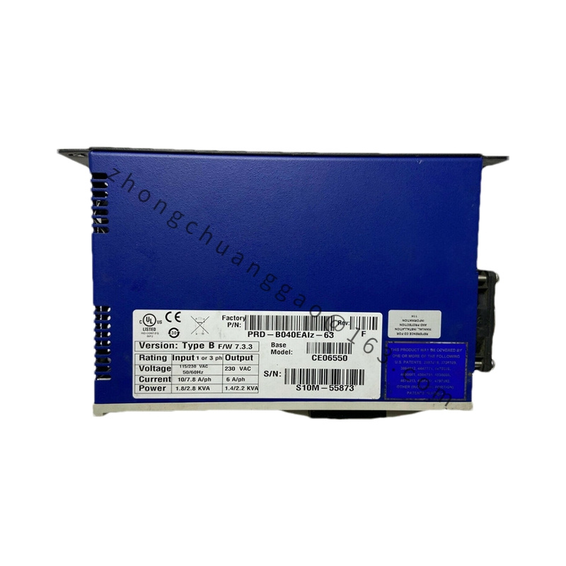
Technical Specifications
- Input Power: Three Phase AC 380–480V, 50/60Hz
- Rated Input Current: 17A continuous
- DC Bus Output Voltage: Fixed 600V DC ±2%
- Regenerative Power Capacity: 30kW maximum bidirectional power transfer
- Power Factor Correction: PF ≥0.99 full load range
- THD Input Current: ≤3% rated load
- Control Auxiliary Supply: DC 24V ±10%
- Communication Interface: CANopen, RS485
- Dimension: 420mm(H) × 150mm(W) × 210mm(D)
- Net Weight: 8.7kg
- Protection Class: IP20
- Operating Temperature: 0°C ~ +45°C
Function Features
- Active power factor correction, suppress grid harmonic pollution
- Bidirectional energy flow: rectify grid AC to DC bus, feed motor braking energy back to power grid
- Real-time DC bus voltage stabilization, eliminate voltage fluctuation under heavy dynamic load
- Multi-stage hardware protection: overvoltage, undervoltage, overcurrent, overheat, phase loss, grid surge
- Real-time operating data upload via bus: input power, regeneration power, DC bus voltage, internal temperature
- Parallel expansion support, multiple PRD modules connected in parallel for higher total regeneration power
- Soft start circuit to avoid grid inrush current during power-on
Performance Parameters
- Voltage regulation precision: ±0.5% DC bus full load variation
- Regeneration response speed: <5ms when braking energy generated
- Inrush current suppression: ≤2 times rated input current at startup
- Efficiency: ≥96.5% at rated operating power
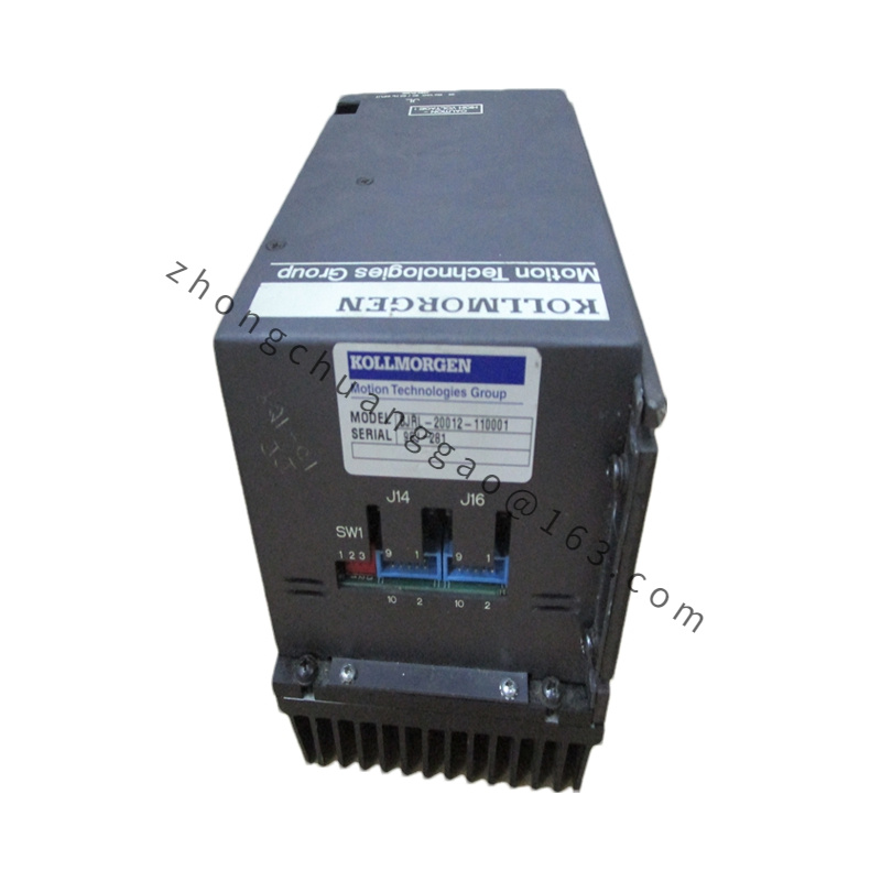
Material Composition
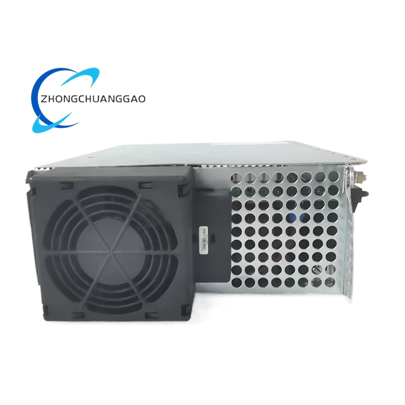
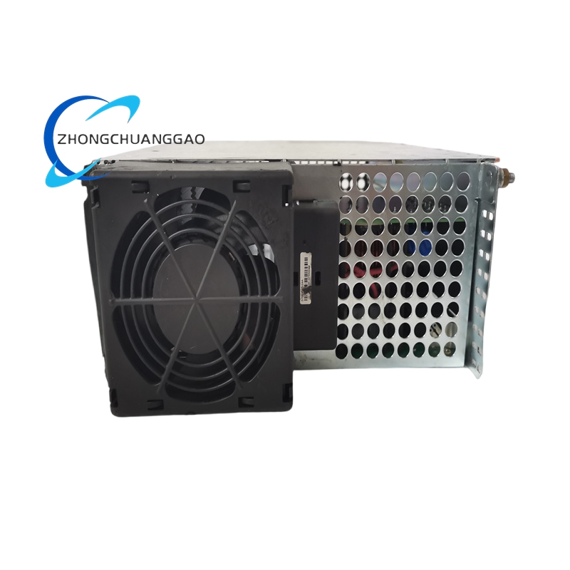
- Main Housing: Thick galvanized steel cabinet with powder coating
- Power Heat Sink: Large-size cast aluminum alloy
- Main Power IGBT: High voltage bidirectional switching power tube
- Filter Inductor Core: Silicon steel laminated low-loss magnetic core
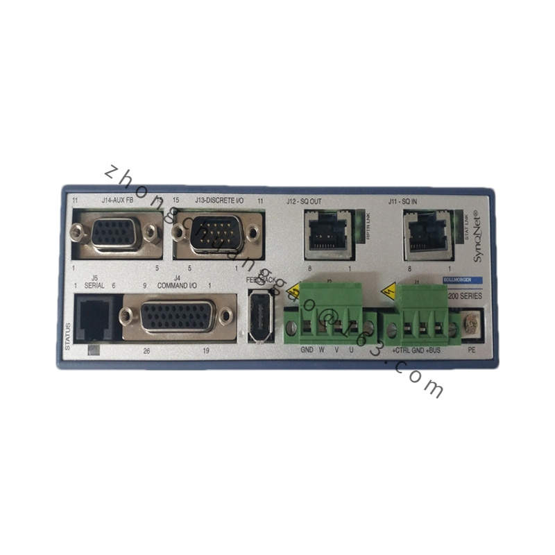
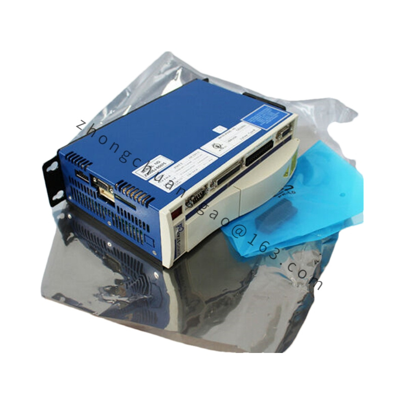
Structural Characteristics
- Vertical cabinet integrated design, top air inlet, bottom air outlet vertical heat dissipation channel
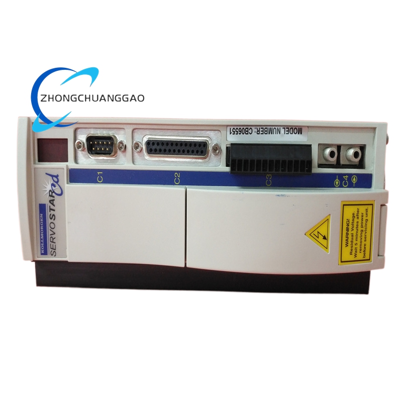
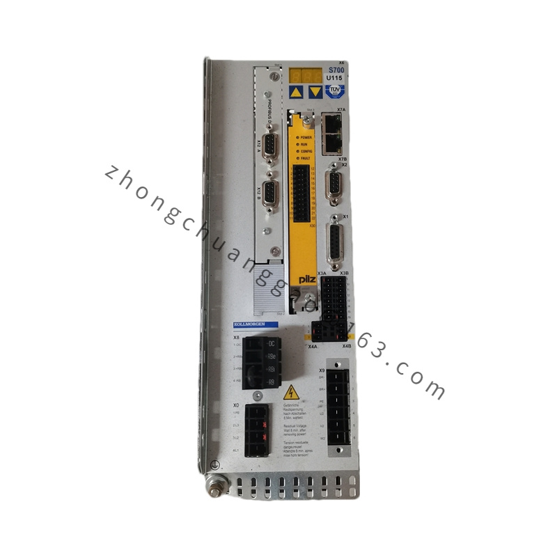
- Front panel integrated digital display for DC bus voltage, operating power, fault code
- Top three-phase AC grid input terminals, bottom DC bus output terminals for drive connection
- Built-in high-capacity EMC filter to reduce grid electromagnetic interference
- Dual cooling fans with temperature-controlled automatic speed adjustment
Working Principle
- Three-phase AC grid input passes EMC filter and soft start circuit to active PFC rectifier stage
- PFC circuit adjusts input current phase to align with grid voltage, maintain power factor near unity
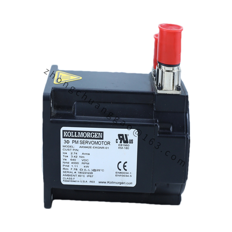
- Rectifier stage generates stable constant 600V DC bus voltage for all connected AKD/S series servo drives
- When motors decelerate/gravity load descends, mechanical energy converts to electrical energy flowing back to DC bus
- PRD inversion stage converts excess DC power back to three-phase AC and feeds into factory power grid
- Internal DSP monitors DC bus voltage in real time, dynamically adjusts rectifier/inverter operating mode
Advantage Highlights
- Eliminates heat generation from braking resistors, reduces cabinet cooling load and fire risk
- High power factor and low harmonic, meets industrial grid power quality standards without additional filter
- Energy saving rate up to 15–30% for high-frequency reciprocating motion equipment
- Parallel expandable architecture, flexible power capacity matching multi-axis system scale
- Stable DC bus voltage eliminates drive overvoltage fault under heavy regenerative load
Applicable Industries
Multi-axis robotic production lines, gantry machine tools, elevator automation, stamping equipment, packaging multi-station transfer lines, crane handling machinery
Installation Requirements
- Vertical cabinet mounting only, install at the top of electrical control cabinet for natural hot air outflow
- Top clearance ≥100mm, bottom clearance ≥80mm for cooling air circulation
- Separate power cable routing from signal control wiring, maintain ≥30cm distance
- Earth wire cross-section ≥6mm² copper conductor
- Mounting plate thickness ≥3mm steel plate, flatness tolerance ≤0.2mm
Usage Precautions
- Grid input must install three-phase circuit breaker with matched rated current
- Do not disconnect DC bus wiring while PRD remains energized
- After power cut, wait minimum 20 minutes for internal high-voltage capacitor complete discharge before maintenance
- Clean cooling fan and heat sink dust every 2 months in dusty workshop environments
- Parallel module quantity limited to maximum 4 units per shared DC bus system
- Ambient humidity must maintain 20–80% non-condensing, avoid cabinet internal water vapor condensation
.jpg)