

Digital guide
You are here:
- Home
- Kollmorgen
- Kollmorgen P01207-NAC
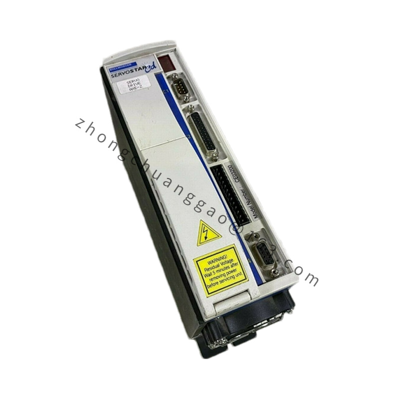
Kollmorgen P01207-NAC
Product Introduction
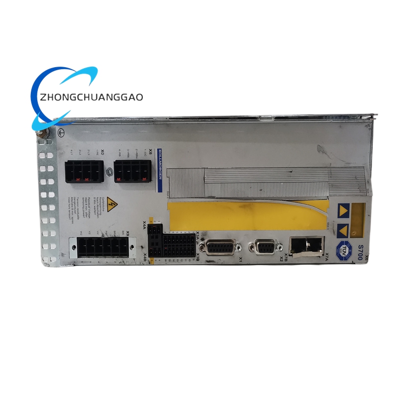
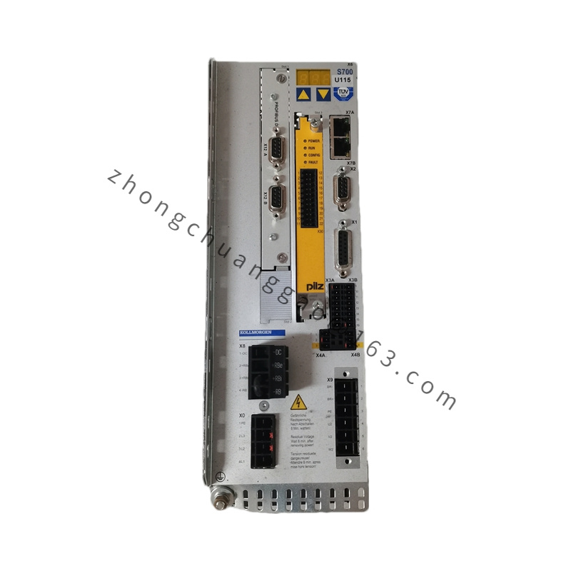
Kollmorgen P series shared DC bus active regenerative power supply module, NAC suffix denotes standard AC grid connection hardware configuration without regional voltage limitation. Matches multi-axis S400/S600/S700 servo drive shared DC bus systems, converts regenerative braking energy from multiple servo axes back to industrial AC power grid to eliminate energy waste and overvoltage fault risks.
Detailed content
Technical Specifications & Core Performance Parameters (Bold Key Data)
- Input AC Mains: Three-Phase AC 208V ~ 480V, 50/60Hz
- Rated Continuous Regenerative Power Capacity: 12kW
- Model Core Current Parameter Code 07: Maximum bidirectional DC bus rated current 70A
- DC Bus Operating Voltage Range: 320VDC ~ 900VDC
- Bidirectional Energy Flow Mode: Rectifier (AC to DC) / Inverter (DC to AC regenerative feedback)
- Power Factor Correction Performance: Input power factor ≥0.99 under full load operating state
- Input Current Total Harmonic Distortion (THD): ≤3% full load
- Communication Interface: CANopen onboard for real-time DC bus voltage monitoring and state feedback
- Physical Dimension: W 130mm × H 410mm × D 270mm
- Net Weight: 7.8kg
- Protection Class: IP20 cabinet internal installation only
- Operating Ambient Temperature: 0°C ~ +40°C full rated power; linear derate 3% per °C above 40°C
- Storage Temperature Range: -25°C ~ +60°C
- Allowable Relative Humidity: ≤85% RH, non-condensing
- Max Operating Altitude: 1000m without power derating; 5% power reduction per extra 1000m elevation
- Certifications: UL, cUL, CE Class B EMC industrial certification
Material Composition
- Outer Cabinet Shell: Thickened cold-rolled steel anti-corrosion black electrophoretic coating
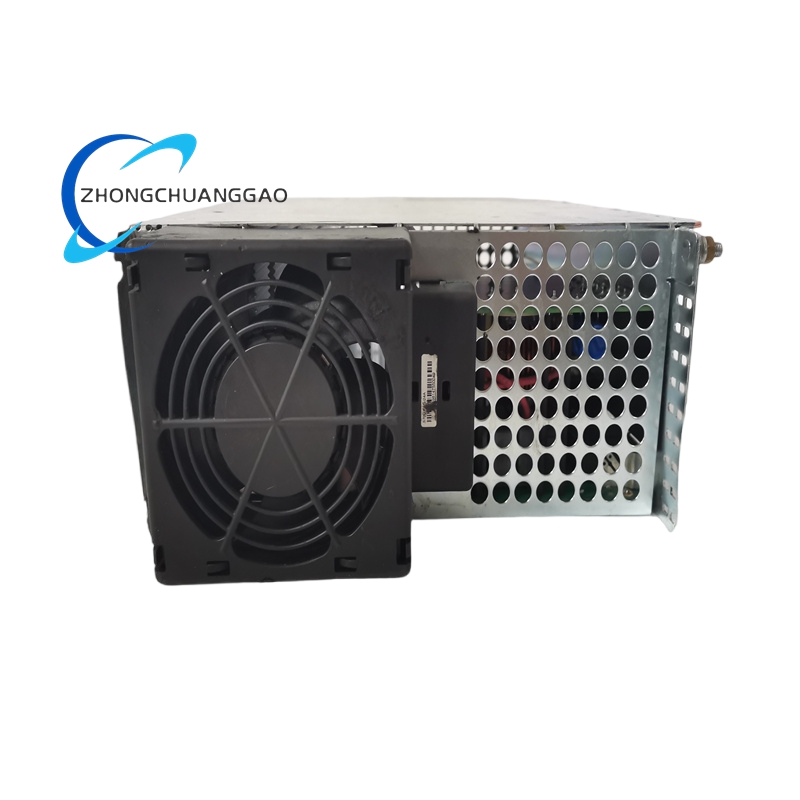
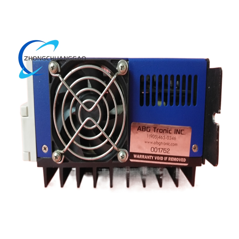
- Main Heat Dissipation System: Large aluminum alloy fin heat sink with built-in variable speed DC cooling fan and replaceable dust filter screen
- Main Control PCB: Multi-layer FR4 high-temperature fiberglass circuit board, industrial grade SMD power components
- Bidirectional Power Switching Device: Silicon IGBT full-bridge rectifier/inverter module with independent temperature thermistor
- Power Terminal Connectors: Heavy-duty nickel-plated copper high-current terminals, flame retardant PA66 insulation housing
- Internal Filter Components: High-capacity three-phase EMC filter inductors, low ESR DC bus energy storage capacitors
Structural Features
- Vertical DIN rail mounting design compatible with standard 35mm industrial cabinet mounting rails
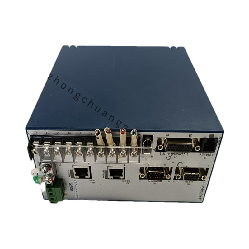
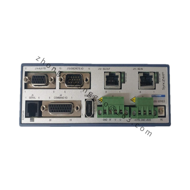
- Separate three independent terminal zones: AC mains input terminal area, shared DC bus output terminal area, signal communication I/O terminal area, complete physical isolation
- Front panel multi-color LED indicator group: Grid Normal, DC Bus Voltage Normal, Regenerative Feedback Running, Over-Temperature Fault, Overcurrent Fault
- Rear built-in variable speed cooling fan with detachable dust filter screen for convenient regular cleaning
- Onboard CANopen communication interface realizes real-time data upload to upper controller for system energy monitoring
- Internal integrated DC bus voltage balance circuit, eliminates DC bus voltage imbalance risk in multi-drive shared bus systems
Working Principle
- Three-phase industrial AC mains input passes built-in three-phase EMC filter and IGBT rectifier circuit to convert AC power to stable high-voltage DC bus power supply for all connected servo drives
- When multiple servo axes execute deceleration braking motion, motor kinetic energy converts back to DC bus regenerative energy and raises DC bus voltage
- Built-in bidirectional IGBT inverter circuit automatically starts when DC bus voltage exceeds preset threshold, converts excess DC regenerative energy back to three-phase AC grid to stabilize DC bus voltage within safe operating range
- DSP digital control chip executes real-time power factor correction algorithm, suppresses input current harmonic distortion and maintains high input power factor
- Real-time monitoring circuit continuously samples AC input current, DC bus voltage and heat sink temperature; hardware protection circuit cuts power flow immediately once parameter exceeds rated safety threshold
- CANopen bus transmits module running state, regenerative power output value and fault code to upper motion controller for centralized system monitoring
Function Characteristics
- Bidirectional active rectifier/inverter structure realizes full energy feedback from multi-axis servo braking to AC grid, reduces overall equipment power consumption
- Built-in power factor correction circuit eliminates low power factor penalty charges from industrial power supply grid operators
- DC bus voltage balance function stabilizes bus voltage during asynchronous acceleration and deceleration of multiple servo axes
- Complete multi-layer hardware protection: Overvoltage, undervoltage, overcurrent, over-temperature, grid phase loss, reverse phase sequence protection
- Real-time regenerative power data upload via CANopen bus for factory energy consumption statistics and equipment operation monitoring
- Support parallel multiple P01207-NAC modules to expand total regenerative power capacity for heavy-load multi-axis production lines
Advantage Highlights
- 12kW large continuous regenerative power capacity adapts to multi-axis frequent start-stop automation production lines with massive braking energy generation
- THD ≤3% ultra-low input harmonic distortion avoids interference with other precision electronic equipment in factory power grid
- High power factor ≥0.99 eliminates industrial power grid reactive power loss and related power fee surcharges
- Active regenerative feedback completely replaces passive braking resistors, eliminates heat dissipation burden and long-term resistor replacement maintenance cost
- CANopen real-time state monitoring realizes remote fault diagnosis and equipment energy efficiency analysis
- Parallel expandable design allows flexible power capacity expansion according to production line axis quantity and load demand
Applicable Industries
Multi-axis lithium battery manufacturing production lines, rotary printing multi-color press equipment, plastic film multi-station slitting machinery, heavy-duty multi-axis CNC machine tools, textile multi-spindle spinning equipment, automated warehousing multi-axis conveying robots
Installation Requirements
- Vertical installation on standard 35mm DIN rail inside sealed electrical cabinet; maintain 120mm minimum top ventilation clearance, 60mm bottom clearance for cooling fan airflow circulation
- Three-phase AC input cable cross-section ≥6mm² copper wire; shared DC bus connection cable cross-section ≥10mm² copper conductor
- Module grounding terminal connected to cabinet main ground bar, grounding resistance ≤4Ω; power cable shield layer single-end grounded at module terminal side
- AC power wiring, DC bus wiring and signal communication wiring laid in three independent separated cable troughs, minimum 20cm separation distance between power and signal lines
- Cabinet forced ventilation system mandatory for 24-hour full-load continuous operation above 40°C ambient temperature
- Install air filter screen at cabinet air intake to prevent metal dust accumulation on module rear cooling fan filter
Usage Precautions
- Disconnect three-phase main AC power supply and wait 20 minutes for high-capacity DC bus capacitors full discharge before disassembling wiring terminals to prevent lethal electric shock hazard
- Forbid short-circuit of DC bus positive and negative output terminals under powered state; instantaneous short-circuit destroys internal bidirectional IGBT power bridge module
- Conduct monthly cleaning of rear cooling fan dust filter screen; blocked filter causes heat sink over-temperature and automatic power reduction protection
- Multi-module parallel shared DC bus system must adopt official equalization wiring scheme to avoid inter-module circulating current damage
- Grid three-phase phase sequence must strictly follow terminal marking; reverse phase sequence triggers permanent module startup fault
- Avoid installation near strong vibration sources such as hydraulic stamping equipment; long-term vibration loosens heavy high-current power terminals
- Ambient environment must be free of corrosive gas, conductive metal dust and oil mist; long-term dust infiltration causes internal circuit short-circuit
.jpg)
.jpg)