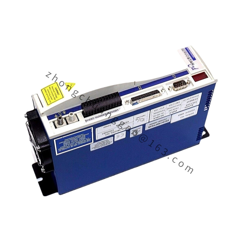
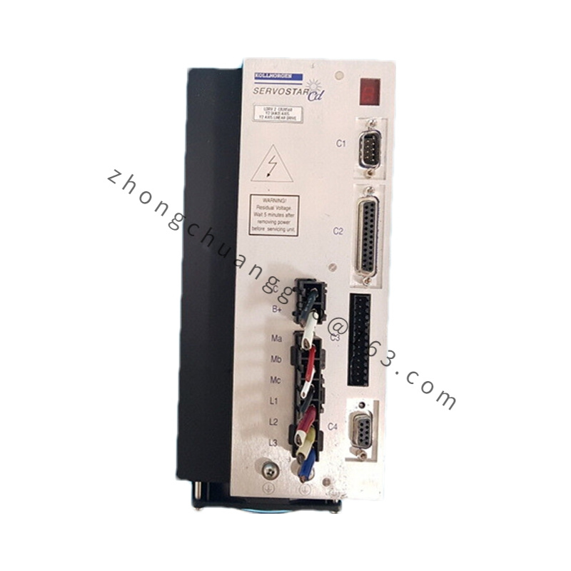
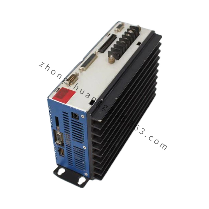
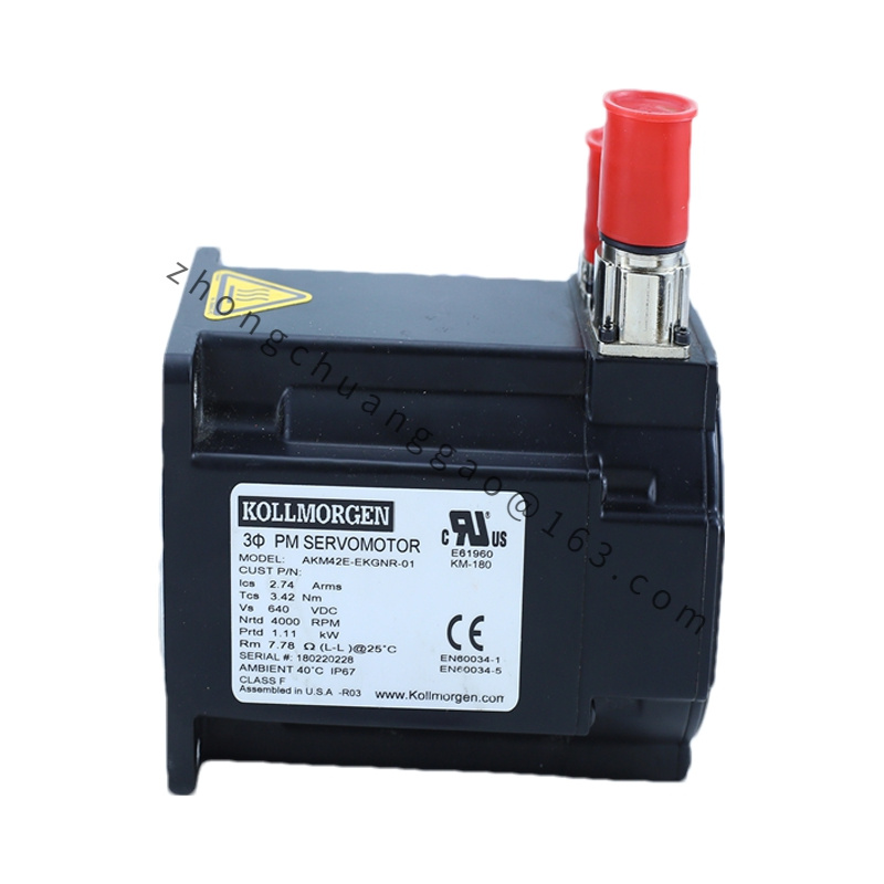
Product Name: LE Iron-Core Direct-Drive Linear Servo Motor (Forcer Segment)
Product Overview:
A 3-phase U-channel iron-core linear motor from the Kollmorgen LE series. It produces linear thrust directly from electrical current without ballscrew, rack or belt. “LE06565-AG” denotes a specific forcer length, stack and connector layout; the magnet track is ordered separately.
Motor Type: 3-phase permanent-magnet synchronous linear motor, iron-core
Continuous Thrust: ≈ 42 N (dependent on stack/thermal rating)
Peak Thrust: ≈ 120 N (short-duty)
Rated Bus Voltage: 320 VDC (230 VAC input class) or 560 VDC (480 VAC class)
Maximum Speed: 2–5 m/s (design dependent, limited by drive and encoder)
Force Constant: ≈ 35 N/A RMS
Back-EMF Constant: ≈ 23 V/(m/s) line-to-line
Pole Pitch: 24 mm typical for LE06 family
Forcer Mass: ≈ 2.8 kg
Forcer Dimensions: ≈ 240 × 120 × 100 mm
Winding Insulation: Class F (155 °C)
Cooling: Natural convection or forced air
Ingress: IP54 forcer coil sealed
Construction & Materials:
Laminated silicon-steel teeth, epoxy-potted copper coils, aluminum alloy housing, rare-earth NdFeB magnet track (separate part), stainless non-magnetic side plates, integral linear encoder scale optional.
Working Principle:
A traveling magnetic field synthesized by the servo drive interacts with the permanent-magnet track via Lorentz force; net force is F = Kt × Iq. Position loop closes through external linear encoder (1 Vpp sin/cos, EnDat or BiSS). No mechanical conversion loss.
Features:
Zero backlash, high stiffness, sub-micron repeatability achievable with fine encoder, cogging cancelled by skewed laminations, high thrust density per footprint.
Air gap 0.6–1.0 mm between forcer and magnet track, alignment tolerance ±0.1 mm over travel. Magnet track must be non-ferrous shielded to avoid attracting chips. Separate power and encoder cables by ≥ 100 mm. Never energize without encoder feedback—runaway risk.


.jpg)
.jpg)