")
Digital guide
You are here:
- Home
- Kollmorgen
- Kollmorgen D20001-00000000
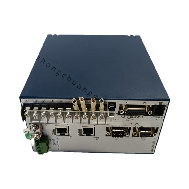
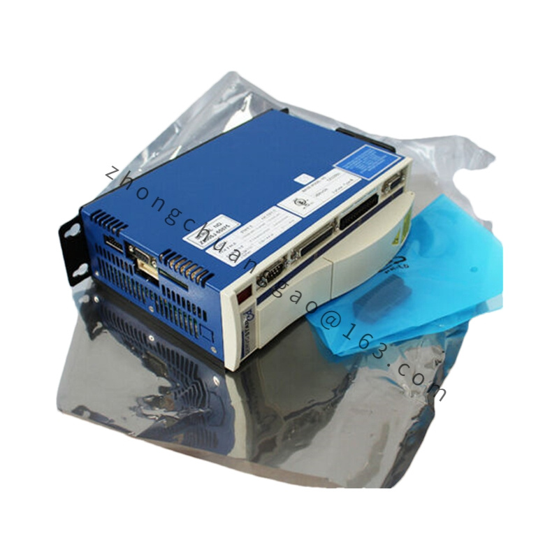
Kollmorgen D20001-00000000
Product Brief Introduction
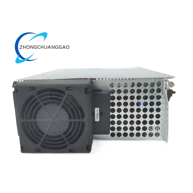
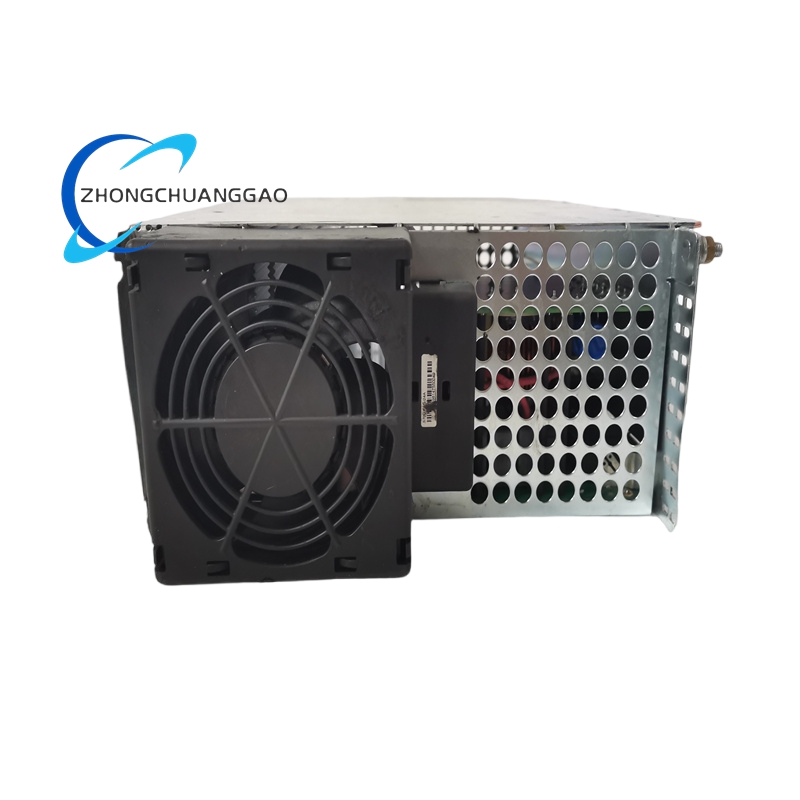
High-power external regenerative braking resistor dedicated for matching Kollmorgen AKD-P high voltage servo drives, used to dissipate excess regenerative energy generated during motor deceleration, vertical axis descent, and rapid reciprocating motion cycles. Full zero suffix denotes standard fixed resistance value and power rating factory pre-assembled resistor module with integrated thermal over-temperature protection switch.
Detailed content
Technical Specifications
- Nominal Resistance Value: 200 Ω ± 2% tolerance
- Continuous Average Dissipation Power Rating: 1000 W
- Peak Instantaneous Energy Dissipation Capacity: 25 kJ single pulse maximum
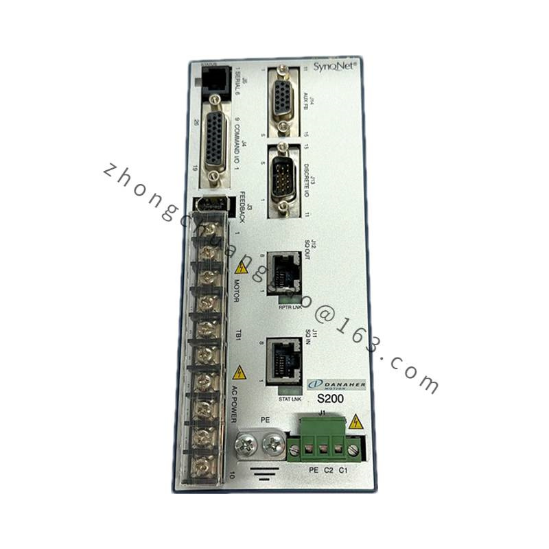
- Operating Voltage Compatibility: Matches AKD-P 208–480 VAC high voltage servo drives DC bus circuit
- Thermal Protection Switch Trip Temperature: 150 °C normally closed contact
- Reset Mode of Thermal Switch: Automatic temperature drop reset at 110 °C
- Wiring Terminal Standard: M6 threaded copper power terminals
- Physical Dimension: 320 mm (L) × 120 mm (W) × 65 mm (D)
- Net Weight: 4.2 kg
- Protection Class: IP20 module housing
- Maximum Surface Operating Temperature: 280 °C at full continuous power load
- Ambient Operating Temperature Range: -10 °C to +45 °C
- Certifications: CE, RoHS 2, UL 60065
Functional Features
- Absorbs motor regenerative back EMF energy during deceleration to suppress DC bus overvoltage fault alarm of AKD-P servo drives
- Built-in bimetallic thermal over-temperature protection switch cuts regenerative circuit connection automatically when resistor surface temperature exceeds 150 °C
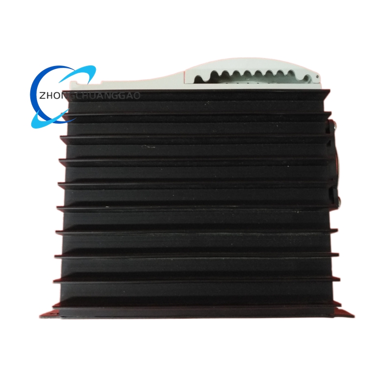
- Integrated aluminum alloy heat sink fin structure enhances passive heat dissipation without auxiliary cooling fan
- M6 large cross-section copper terminals support thick gauge power cable connection to minimize wiring contact resistance
- Ceramic resistance core with anti-oxidation coating maintains stable resistance value under long-term high-temperature cyclic operation
- Standard mounting holes compatible with electrical cabinet internal vertical rack installation layout
Performance Highlights
- 25 kJ single pulse peak energy capacity handles high-inertia mechanical system rapid deceleration energy release requirements
- ±2% tight resistance tolerance ensures consistent regenerative energy dissipation efficiency across full operating temperature range
- Thermal protection switch prevents permanent resistor core burnout under continuous overload regenerative energy conditions
- Low temperature drift resistance material limits resistance value variation to ≤ 5% between -10 °C and 280 °C surface temperature
Material Composition
- Resistance Core: Metal alloy wire wound ceramic tubular resistor element with high-temperature anti-corrosion glaze coating
- Heat Sink Housing: Extruded aluminum alloy finned heat sink with black oxidation heat radiation coating
- Thermal Protection Component: Bimetallic strip temperature switch with high-temperature resistant insulating housing
- Terminal Hardware: Tinned solid copper M6 threaded terminal posts
- Mounting Bracket: Cold-rolled steel sheet powder-coated anti-rust fixing frame
Structural Characteristics
- Horizontal finned aluminum heat sink body with uniform fin spacing for natural convection air flow circulation
- Independent internal compartment separation for ceramic resistance core and thermal switch assembly to avoid heat conduction interference
- Four symmetrical M5 mounting screw holes on base bracket for fixed installation on cabinet metal backplane
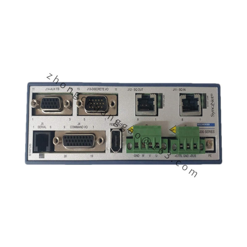
- Two front-end M6 power terminals clearly labeled RB+ and RB- for direct connection to AKD drive external braking resistor ports
- Secondary two-pin signal terminal for thermal switch fault signal feedback to upper PLC safety circuit
Working Principle
- During servo motor deceleration or vertical load descent, motor operates as generator to feed regenerative electrical energy back into drive DC bus circuit, raising DC bus voltage
- When DC bus voltage exceeds drive internal regenerative circuit threshold, drive power switching device connects D20001 resistor assembly across DC bus positive and negative poles
- Regenerative electric current flows through 200 Ω metal alloy resistance core, converting excess electrical energy into thermal energy dissipated via aluminum heat sink fins into cabinet ambient air
- Bimetallic thermal switch monitors resistor core surface temperature continuously; opens regenerative circuit connection upon 150 °C over-temperature threshold crossing to stop energy dissipation and prevent component burnout
- Thermal switch auxiliary contact transmits over-temperature fault digital signal to external PLC safety interlock circuit for equipment alarm and motion stop trigger
Advantage Highlights
- Factory pre-calibrated resistance value eliminates on-site resistance selection calculation for high-inertia servo axes
- Integrated thermal protection eliminates requirement for external independent temperature monitoring sensor hardware
- High peak energy capacity covers heavy-duty rapid reciprocating motion applications where drive internal 20 W built-in braking circuit is insufficient
- Standard mechanical mounting footprint compatible with all AKD-P series high voltage drive cabinet layout designs
Applicable Industries
Vertical lifting automated storage racks, heavy-duty gantry robotic systems, metal cutting high-inertia spindle axes, lithium battery large roll unwinding equipment, automated stamping press feeding axes, packaging heavy pallet conveying machinery
Installation Requirements
- Install vertically inside electrical control cabinet with minimum 100 mm top and bottom ventilation air gap around heat sink fins
- Maintain minimum 200 mm horizontal separation distance between resistor assembly and servo drive power modules to avoid heat radiation overheating drive electronics
- Power connection cable cross-section minimum 4 mm² copper shielded cable to reduce wiring power loss
- M6 terminal screw tightening torque controlled at 4 N·m to prevent loose wiring contact resistance heat generation
- Thermal switch signal wiring must connect to PLC 24 VDC isolated digital input terminal for safety fault interlock logic
Operation & Maintenance Precautions
- Do not touch resistor heat sink surface within 30 minutes after equipment shutdown; residual surface temperature exceeds 200 °C causing burn injury
- Cabinet ventilation fan mandatory for continuous full-power regenerative operation; blocked airflow triggers frequent thermal switch tripping
- Regularly clean aluminum heat sink fin dust accumulation every 2 months; dust layer reduces heat dissipation efficiency by over 40%
- Never short-circuit RB+ and RB- power terminals; short-circuit generates instantaneous extreme high current destroying drive power module
- Avoid mounting resistor assembly adjacent to plastic wiring harnesses; long-term heat radiation melts cable insulation layer
