Technical Specifications
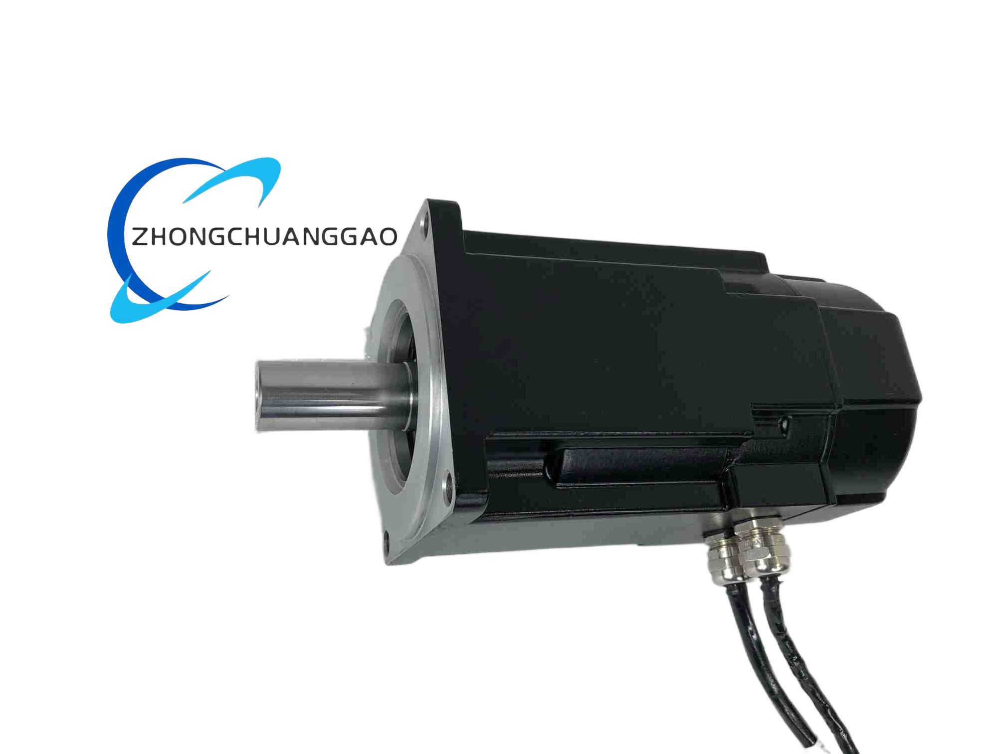
Frame size AKM4, 130 mm IEC square flange. Standard S stack length. Continuous stall torque 4.77 Nm. Peak torque 14.3 Nm. Rated speed 3000 rpm. Maximum speed 5000 rpm. Continuous current 4.0 Arms. Peak current 12.0 Arms. Rotor inertia 0.00087 kg·m². Torque constant 1.19 Nm/Arms. Back-EMF constant 125 V/krpm. Winding code AN, 240 V class. Feedback resolver, multipole analog type. Shaft keyed, no holding brake. Connector fixed straight type, rear or top exit according to mounting. Protection IP65 with shaft seal and sealed connectors. Insulation class F, 155°C. Ambient temperature 0°C to 40°C for full torque, derated to 55°C. Weight approximately 5.4 kg.
Functional Features
Skewed stator for low cogging. Resolver feedback resistant to dust, vibration and electromagnetic noise. Keyed shaft for positive coupling to pulleys, gears and couplings. IP65 construction for washdown and coolant exposure. Integrated thermal sensor for overtemperature protection. Compatible with Kollmorgen AKD, S300 and S700 servo drives.
Application Scenarios
CNC feed and positioning axes. Injection-molding and die-casting ejector motions. Printing, converting and paper-processing machinery. Material-handling gantries. Robotic joint actuators.
Performance Parameters
4.77 Nm continuous torque, 14.3 Nm peak torque, 3000 rpm rated speed, 12.0 Arms peak current, resolver position feedback, IP65 sealing.
Material Composition
Aluminum alloy housing with powder-coated finish. Chrome-plated hardened alloy-steel shaft. Sintered NdFeB rotor magnets with nickel-copper-nickel coating. Low-loss silicon-steel stator laminations with Class-F copper winding. Double-row angular-contact ball bearings with lifetime grease. Nitrile rubber shaft seal.
Structural Characteristics
130 mm square flange with 100 mm pilot and four M8 mounting holes. 19 mm shaft diameter, 6×6 mm keyway per DIN 6885. Rear resolver and fixed straight power/feedback connectors. Finned housing for natural convection.
Working Principle
The servo drive supplies three-phase sinusoidal current to the stator. The resolver measures rotor angle and returns position to the drive. The drive executes field-oriented control of current, speed and position loops to regulate torque and motion accuracy.
Installation Requirements
Mount on a rigid machine frame with mounting-surface flatness within 0.05 mm. Use a keyed coupling or pulley with interference fit and setscrew. Align the load shaft to within 0.05 mm TIR. Tighten flange bolts to 24 N·m. Provide at least 50 mm clearance around the motor for ventilation. Connect resolver and power cables using the specified straight connectors.
Usage Precautions
Radial load at shaft midpoint must not exceed 250 N. Axial load must not exceed 100 N. Do not operate above 5000 rpm. Do not direct high-pressure wash water at connectors. Verify drive current rating against 12.0 Arms peak requirement. Replace the shaft seal if wear or oil leakage appears.


.jpg)