Digital guide

You are here:

Kollmorgen 60WKS-CE240/06-PB

Product Overview:
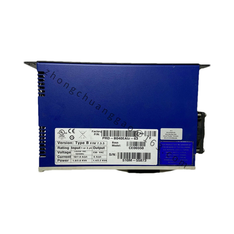
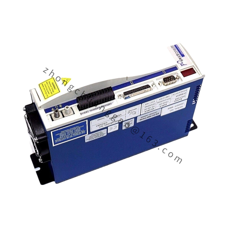
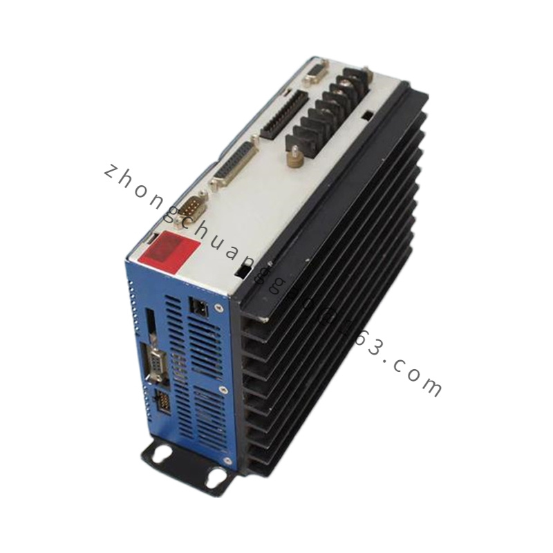
The 60WKS-CE240/06-PB is a ceramic-encapsulated wirewound power resistor from Kollmorgen’s 60WKS product line. These resistors are designed for use as dynamic braking resistors in servo drive systems, dissipating regenerative energy from the motor during deceleration. The “CE” denotes ceramic encapsulation for high thermal durability. “240” indicates 240 ohms resistance. “06” indicates ±6% tolerance. “PB” denotes the terminal/lead configuration.

Detailed content

Key Specifications:

Parameter Value
Resistance Value 240 Ω (±6%)
Power Rating (Continuous) 60 W
Peak Power (10 sec) 600 W (10× rated)
Resistance Tolerance ±6%
Temperature Coefficient (TCR) ±75 ppm/°C
Encapsulation Ceramic (CE)
Terminal Type PB (Pigtail/Bolt leads)
Max Operating Voltage 500 VDC
Max Operating Temperature +275°C (resistor element)
Insulation Resistance > 100 MΩ at 500 VDC
Inductance < 5 μH (low-inductance design)
Dimensions (Approx.) 25 mm × 25 mm × 75 mm (L×W×H)
Weight Approximately 0.12 kg (0.26 lb)

Construction & Materials:

  • Resistive Element: Nichrome (NiCr 80/20) wirewound on ceramic core
  • Encapsulation: High-purity alumina ceramic, hermetically sealed
  • Terminals: Tin-plated copper pigtail leads (PB type)
  • Coating: Ceramic body provides inherent flame retardancy (UL 94 V-0 equivalent)
  • Mounting: Free-standing or panel-mount via terminal leads

Performance Parameters:

Parameter Value
Max Continuous Current 0.5 A (√(60W/240Ω))
Peak Current (10 sec) 1.58 A
Max Voltage Drop at Rated Current 120 VDC
Thermal Resistance (Rth) < 15 °C/W (element to ambient, free air)
Derating Factor 1.5% per °C above 70°C ambient
Life Expectancy > 50,000 hours at rated power
Pulse Handling 10× rated power for 10 seconds, 50 cycles max

Advantages:

  • Ceramic encapsulation — superior thermal shock resistance vs. aluminum-housed resistors
  • Low inductance (< 5 μH) — critical for high-frequency PWM switching in servo drives
  • 240 Ω / 60 W — standard value for 240–480 VDC bus servo systems
  • ±6% tolerance — adequate for braking applications where exact resistance is less critical than power handling
  • UL recognized component — when used with UL-listed drives, system maintains UL compliance

Applicable Industries:

  • Servo Drive Systems — dynamic braking for AKD, AKM, and compatible drives
  • CNC Machines — rapid deceleration energy dissipation
  • Elevators & Lifts — regenerative energy management
  • Cranes & Hoists — overload braking energy absorption
  • Wind Turbines (pitch control) — emergency braking circuits

Installation Requirements:

  • Mount in well-ventilated area — minimum 50 mm clearance on all sides for airflow
  • Do not mount near flammable materials — resistor surface reaches 200°C+ at full load
  • Terminal leads (PB) — crimp or solder to drive braking resistor terminals
  • Wire gauge: minimum 18 AWG for 60 W continuous duty
  • If multiple resistors in parallel, ensure equal lead lengths for current sharing

Usage Notes:

  • This is a braking resistor, NOT a load resistor — do not use for continuous motor loading
  • Verify drive braking chopper voltage matches resistor voltage rating (500 VDC max)
  • At 480 VDC bus, braking voltage can exceed 700 VDC during regeneration — add external clamp circuit if bus > 500 VDC
  • Do not exceed 600 W peak for more than 10 seconds — element will overheat
  • Resistance drift at high temperature: expect +3% to +5% increase at 200°C element temperature

You may also like