Digital guide
You are here:
- Home
- Kollmorgen
- KKollmorgen BDS4A-210J-WO
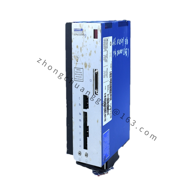
KKollmorgen BDS4A-210J-WO
Product Brief Introduction
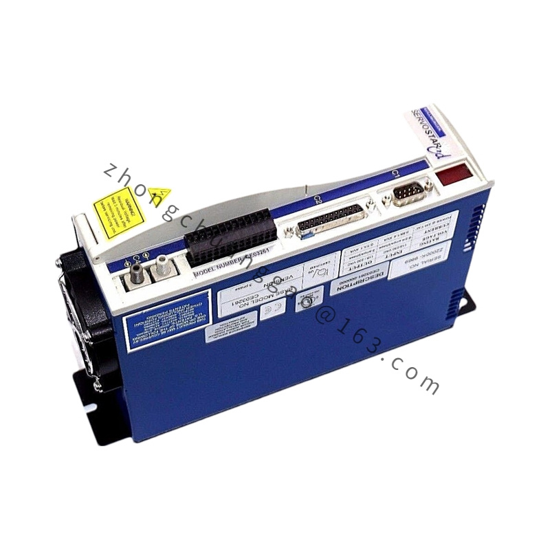
Single-axis compact digital servo drive belonging to Kollmorgen classic BDS4 low-voltage drive series, dedicated driving B-series brushed DC servo motors. Suffix 210J defines maximum continuous output current specification; WO suffix indicates standard open-frame cabinet-only installation version without integrated housing enclosure.
Detailed content
Technical Specifications
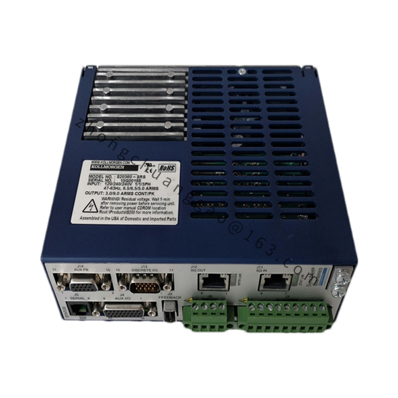
- Input Power Supply: 24–90 VDC unregulated DC bus input
- Continuous Output Current: 10 Arms DC
- Peak Output Current: 20 Arms DC, 1-second maximum duty cycle
- Control Loop Refresh Rate:
- Current Loop: 4 μs, maximum bandwidth 3.2 kHz
- Speed Loop: 120 μs, maximum bandwidth 1.1 kHz
- Position Loop: 250 μs, maximum bandwidth 0.6 kHz
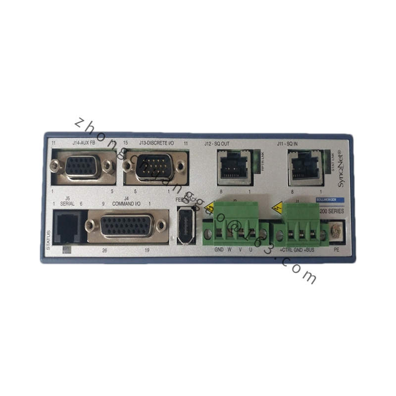
- Feedback Signal Supported: A/B/Z quadrature incremental encoder (5 V line driver output), tachometer analog signal
- Built-in I/O Resources: 8 isolated digital inputs, 4 digital outputs, 1 analog input 0–10 V, 1 analog output 0–10 V
- Communication Interfaces: RS232 service port, CANopen industrial bus standard
- Safety Function Hardware: Hardware overcurrent lockout, overvoltage protection, thermal shutdown, short-circuit phase protection
- Physical Dimension: 108 mm (W) × 155 mm (H) × 42 mm (D)
- Net Weight: 1.45 kg
- Protection Rating: IP00 open frame (must be fully installed inside sealed electrical cabinet)
- Operating Ambient Temperature: 0 °C to +50 °C; 2% power derate per °C above 40 °C
- Storage Temperature Range: -40 °C to +85 °C
- Certifications: UL 61800, CE, RoHS 2
Functional Features
- Full digital three-loop closed-loop control algorithm without analog circuit drift, stable long-term positioning precision
- One-click automatic inertia identification and gain auto-tuning, compatible with 500:1 load inertia matching range
- CANopen bus multi-axis synchronous motion control, supporting electronic gearing and cam curve interpolation
- RS232 serial port connects to Kollmorgen WorkBench software for parameter configuration, fault log reading, firmware upgrade
- Isolated 24 V digital I/O with optical coupling eliminates ground loop interference from field sensors
- Built-in dynamic braking circuit for rapid motor deceleration; compatible with external braking resistor expansion for high-inertia loads
- Real-time fault storage module records 100 historical alarm records with timestamp for equipment failure diagnosis
Performance Highlights
- Ultra-low speed speed ripple control algorithm ensures stable rotation speed below 1 rpm without jitter for precision micro-positioning
- Compact open-frame structure minimizes cabinet space occupation for multi-axis miniature automation systems
- Full digital current limiting circuit prevents permanent motor armature burnout under stall overload conditions
- 85,000-hour MTBF under rated operating environment and load conditions
- Compatible with all Kollmorgen B-series brushed DC servo motors without encoder hardware modification
Material Composition
- Core Circuit Board: FR4 flame-retardant double-sided PCB with lead-free tin surface finish
- Power Switching Component: MOSFET power transistor array bonded on aluminum alloy heat sink
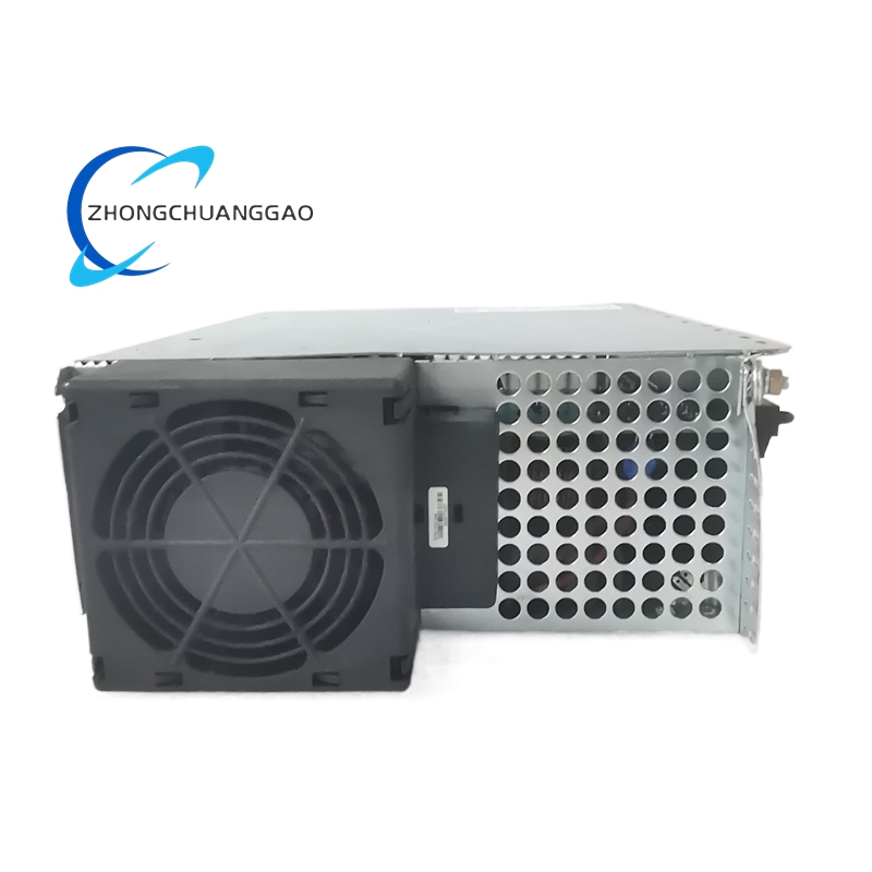
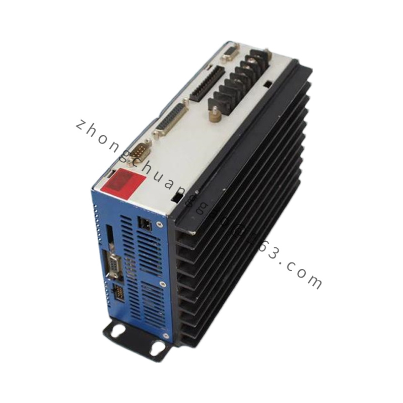
- Heat Dissipation Structure: Extruded aluminum fin heat sink without protective outer shell (WO open-frame design)
- Terminal Connectors: Gold-plated copper alloy screw terminals for power, signal and communication wiring
- Isolation Components: 2500 V optical couplers separating power circuit and control signal circuit
- Fixing Hardware: Cold-rolled steel mounting brackets with anti-rust black powder coating
Structural Characteristics
- Open exposed circuit layout without plastic outer housing; all power semiconductors directly exposed for passive heat dissipation
- Standard vertical cabinet mounting hole layout, uniform hole pitch matching DIN cabinet backplane installation standards
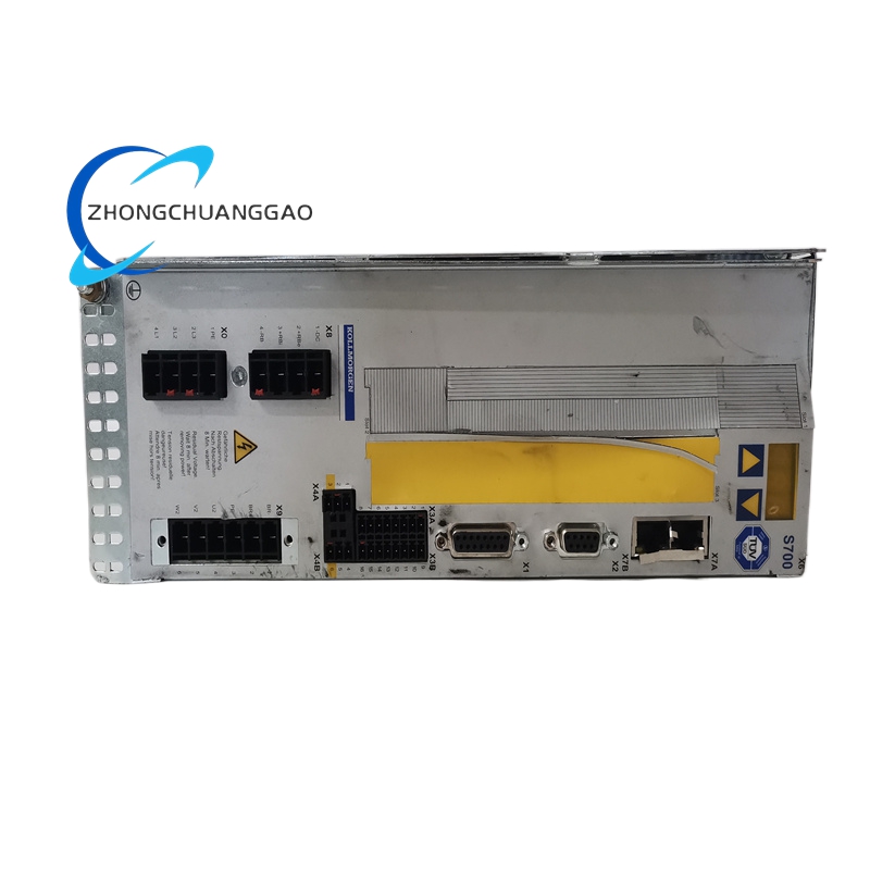
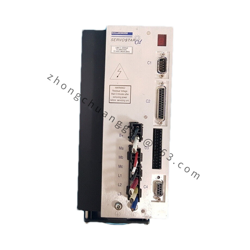
- Independent partition layout: DC power terminal zone, motor armature output zone, encoder feedback port, CAN bus communication port, digital I/O terminal zone
- Rear side integrated large-area aluminum heat sink for heat radiation of high-power MOSFET components
- Front panel embedded LED indicator lights for power status, bus communication, drive enable, fault alarm, output current overload
Working Principle
- External 24–90 VDC power supply inputs direct current to drive internal power conversion circuit to supply DSP control chip and MOSFET power stage
- Upper motion controller sends torque/speed/position command via CANopen bus or analog voltage input
- Drive receives incremental encoder quadrature pulse signal from B-series servo motor to calculate real-time rotor speed and position deviation value
- DSP controller executes PID three-loop operation to generate PWM modulation signal, driving MOSFET bridge circuit to output adjustable DC current to motor armature
- Internal sampling circuit monitors DC bus voltage, output current, heat sink temperature in real time; automatically triggers protection lockout upon overvoltage, overcurrent, overtemperature and short-circuit faults
- Dynamic braking circuit consumes regenerative energy generated by motor deceleration through internal power resistance to suppress DC bus voltage surge
Advantage Highlights
- Open-frame WO version reduces product cost compared to fully enclosed housing models for cabinet-integrated equipment manufacturers
- Unified WorkBench configuration software shared with AKD series drives, reducing engineer learning and training cost
- Wide 24–90 VDC wide voltage input range adapts to battery-powered mobile equipment and industrial low-voltage power supply systems
- Hardware current limit protection avoids frequent motor carbon brush burnout under long-term stall working conditions
- CANopen bus interface supports distributed multi-axis control without expensive dedicated motion control hardware
Applicable Industries
Desktop optical inspection equipment, laboratory automation positioning stages, portable battery-powered testing machinery, miniature medical diagnostic devices, small textile tension control axes, compact packaging marking equipment, semiconductor micro-valve actuators, educational laboratory motion training platforms
Installation Requirements
- Mandatory full installation inside sealed dust-proof electrical cabinet; open IP00 frame cannot be exposed to workshop air, dust or liquid splash
- Maintain minimum ventilation clearance: 40 mm top gap, 30 mm bottom gap, 15 mm left/right side gap between adjacent drives
- DC input power cable cross-section ≥ 2.5 mm² shielded copper cable; cable shield single-point connected to cabinet grounding busbar
- Motor encoder feedback wire must adopt shielded twisted pair cable to avoid PWM power interference causing signal pulse loss
- Vertical mounting orientation only; horizontal or upside-down installation prohibited to block heat sink natural convection airflow
Operation & Maintenance Precautions
- Disconnect DC input power and wait 5 minutes for internal bus capacitor complete discharge before touching exposed PCB circuit components
- Regularly clean aluminum heat sink fins every 2 months to remove accumulated dust blocking heat dissipation, preventing overtemperature faults
- All wiring terminals must maintain tightening torque of 0.9 N·m; loose terminals generate high contact temperature and burn PCB pads
- Firmware upgrade only through official Kollmorgen WorkBench software; third-party firmware invalidates product warranty
- Inductive loads connected to digital output terminals must be fitted with freewheeling flyback diodes to eliminate voltage spike damage to drive internal circuit
.jpg)