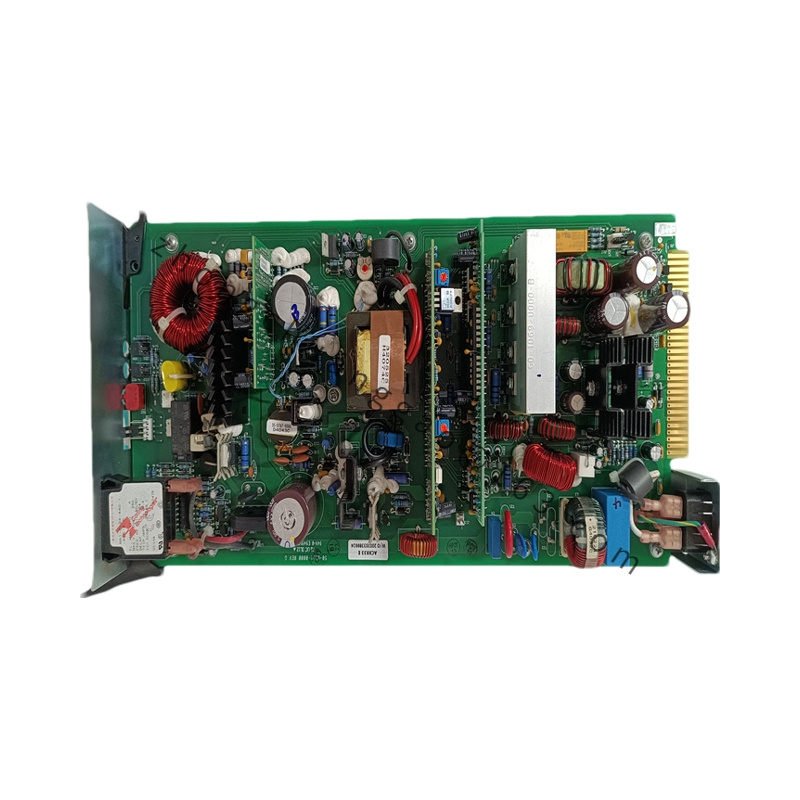
Honeywell CC-TDOB11
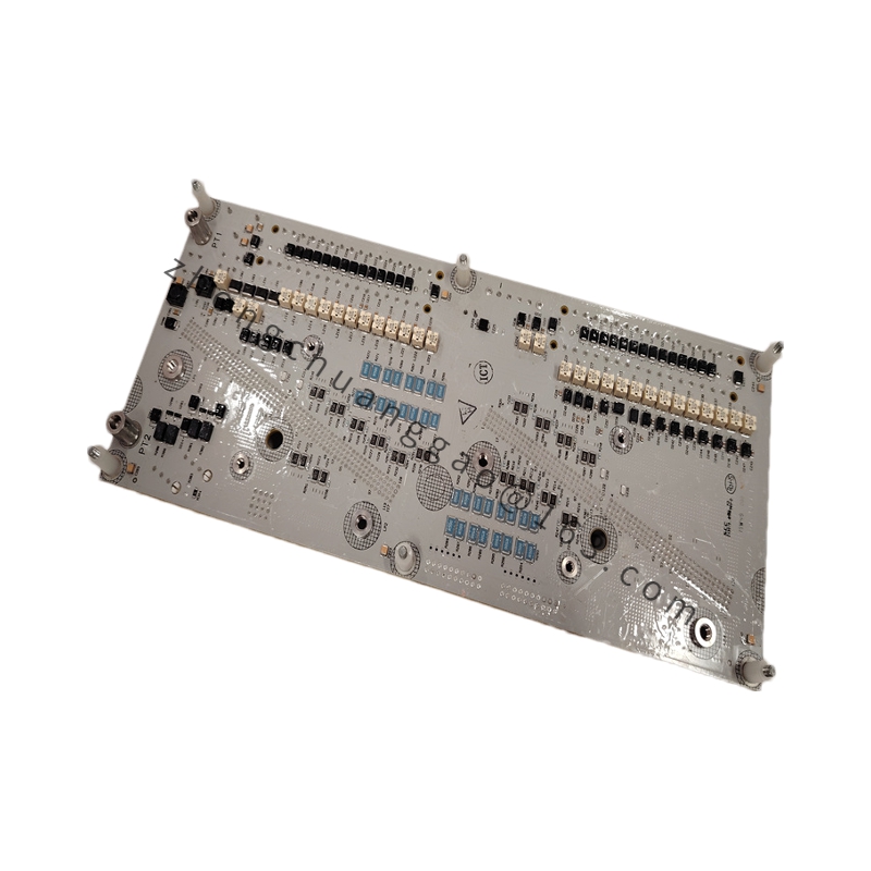
Product Name: 32-Channel Redundant Digital Output IOTA (Termination Assembly)
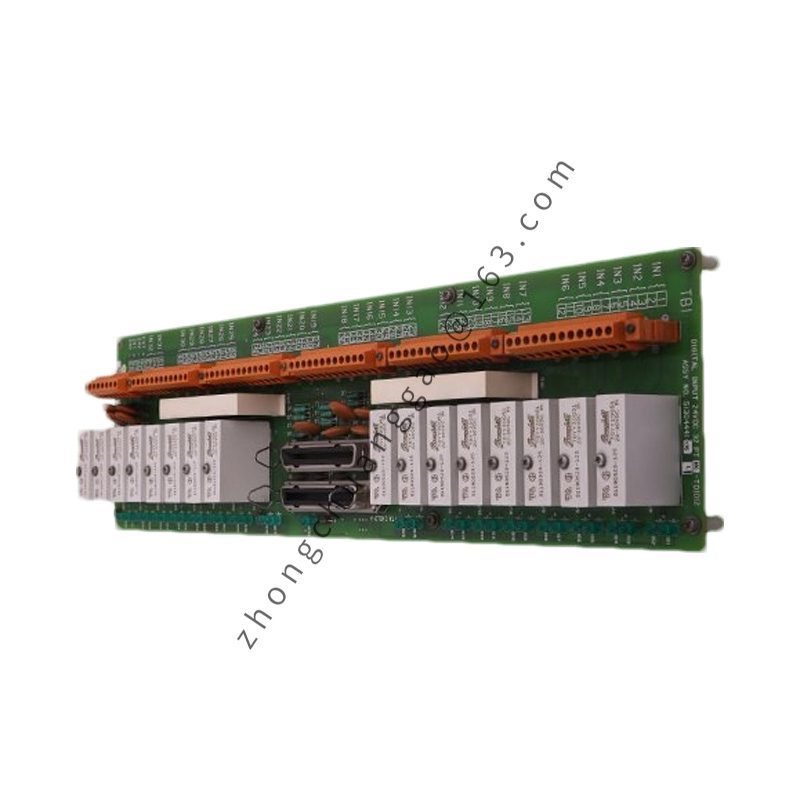
Product Overview: The CC-TDOB11 is a redundant Digital Output IOTA termination assembly within Honeywell’s Experion Series C I/O family. It provides a high-integrity termination platform for 32-channel 24 VDC bussed output systems, supporting dual I/O module configuration on a single 12-inch base for hot standby redundancy at the field termination level.
Detailed content
Key Technical Specifications:
- Model: CC-TDOB11
- Type: Digital Output IOTA (Redundant)
- Origin: USA
- Channels: 32 channels
- Nominal Voltage: 24 VDC
- Output Type: Bussed current sourcing
- Redundancy: Dual I/O module support (true redundant pair)
- Field Power Distribution: Internal bussed 24 VDC across all output channels
- Wiring Terminals: Two-level detachable terminal blocks
- Wire Size: Up to 12 AWG (2.5 mm²)
- Dimensions: 12 inch (304 mm) base
- Weight: 5.0 kg
- Operating Temperature: 0°C to +60°C (extended -40°C to +70°C variant available)
- Power Consumption: Passive termination (no internal load)
- Electronic Protection: Built-in short-circuit protection – no external fusing required
- Hot Swap: Yes (module replacement without field signal interruption)
Functional Features:
- True redundant pair configuration – seamless failover without process interruption
- Electronic short-circuit protection eliminates dependency on external fusing
- Vertical mounting structure improves airflow and cable routing
- Channel-level fault isolation prevents cascading failures
- Maintains signal continuity during module exchange operations
Working Principle: The IOTA is a passive termination base hosting two digital output modules in a redundant pair. 24 VDC field power is distributed through internal bussed pathways. If the active module fails, the standby module instantaneously takes over output control without signal interruption. Built-in electronic protection circuits isolate fault conditions at the channel level.
Application Scenarios: Refinery automation, offshore production systems, and large chemical plants where uninterrupted discrete output control is critical. Eliminates downtime during module failure or maintenance.
Installation & Usage Notes:
- Mount vertically on a standard grounding DIN rail inside the terminal cabinet; verify integrated chassis grounding clamps are locked onto bare metal rail.
- Wire the 32 field loads to the screw-clamp terminal blocks.
- Maintain physical segregation between 24 VDC discrete output wires and high-voltage AC lines.
- Slide matching Series C digital output modules into guide slots until retaining mechanisms lock – misalignment damages interface connectors.
- Allow at least 50 mm of unobstructed clearance around the assembly perimeter for convective airflow.
- Verify redundant module synchronization before commissioning.
- Confirm active module status indicators before removal during live maintenance.
- Do not overload shared bussed channels beyond rated current limits.


.jpg)
.jpg)
.jpg)