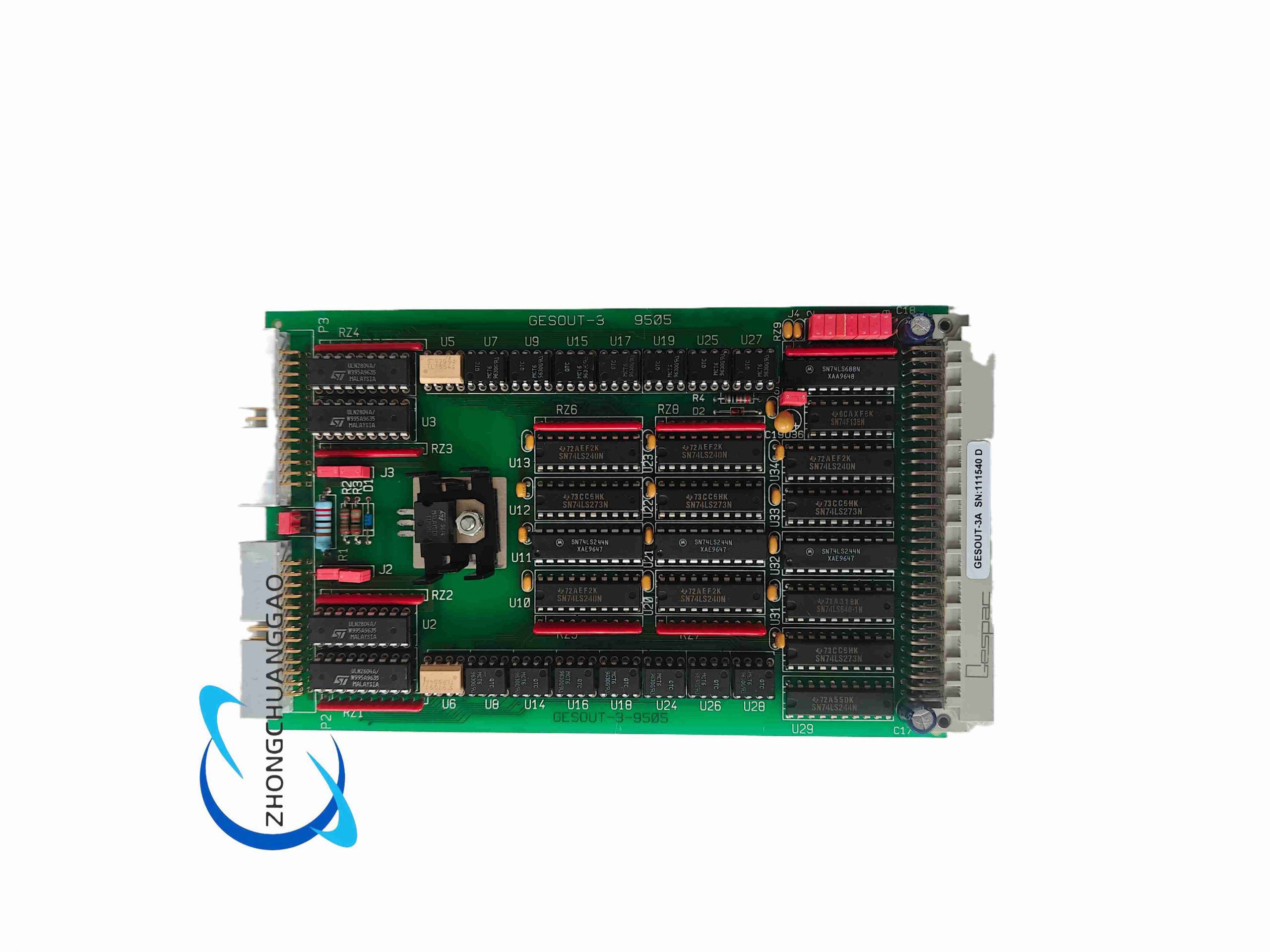
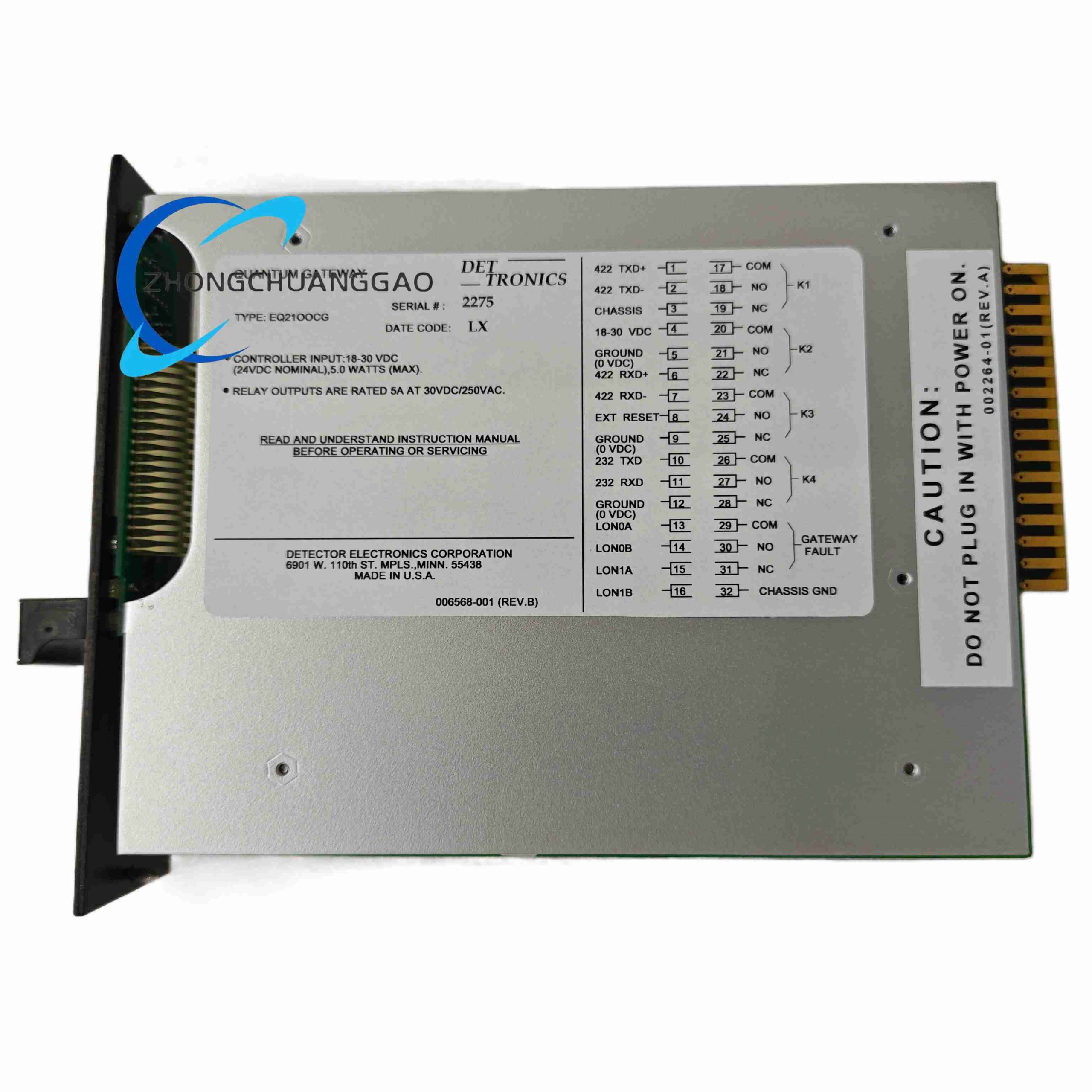
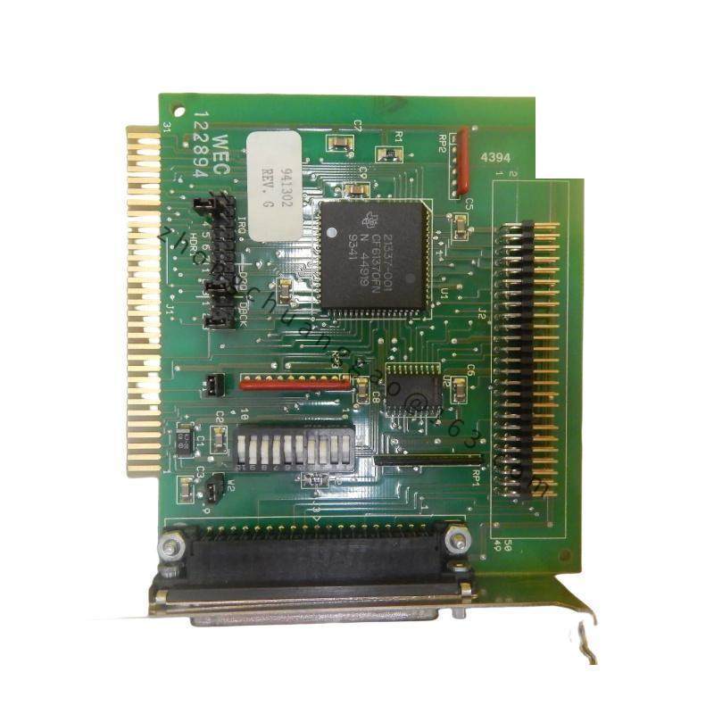
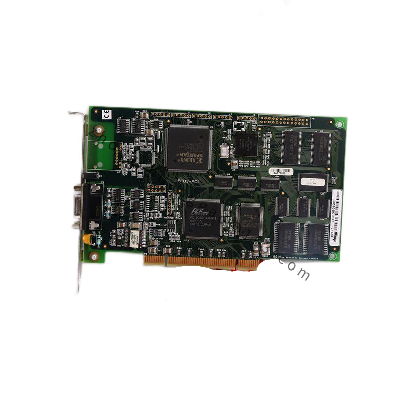
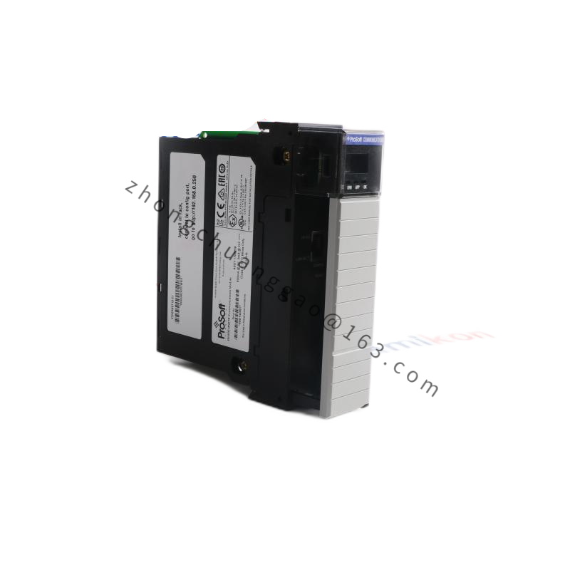
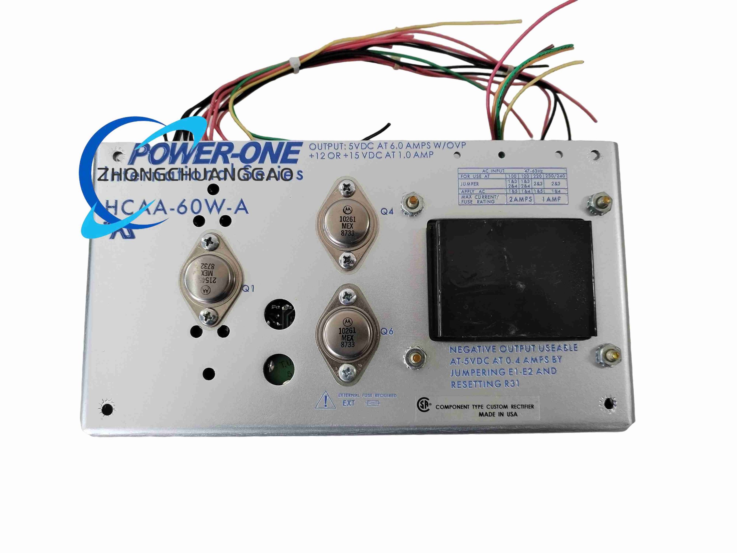
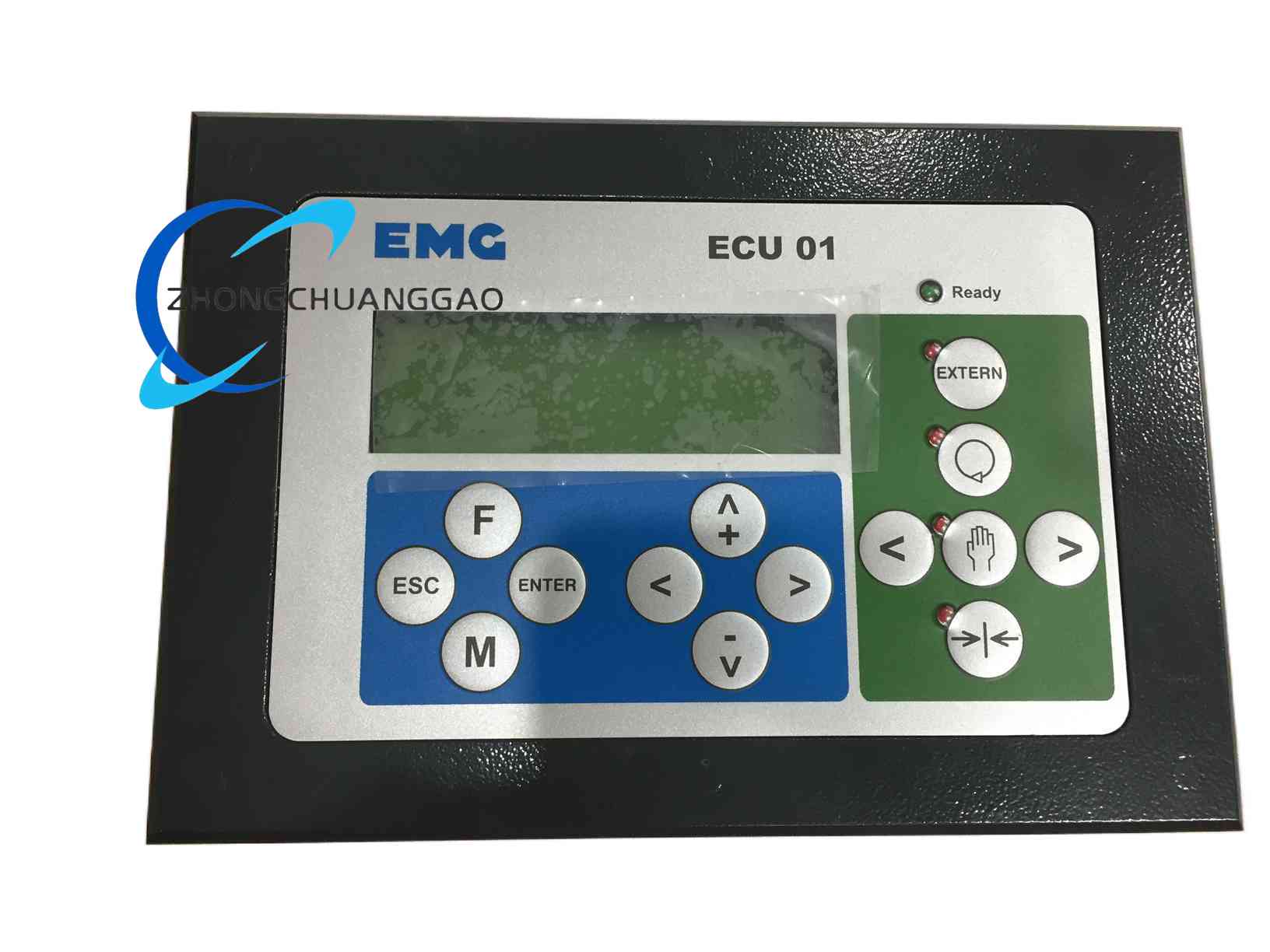
Technical Specifications: Channel count, output type (relay, transistor, or analog), voltage level, current rating, and isolation rating are defined by the module label and the host system manual. Modules of this class support discrete on/off switching or scaled analog output referenced to the system common or an isolated supply.
Functional Features: Direct interfacing between the control logic and field devices; indicator LEDs showing channel state; screw-terminal or plug-in wiring for rapid installation; modular form factor allowing replacement without disturbing adjacent wiring; diagnostics reported to the host for fault detection.
Application Scenarios: DCS and PLC output stages; alarm and indication panels; actuator and solenoid valve control; machine status signaling; test rigs and process skids requiring multiple controlled outputs.
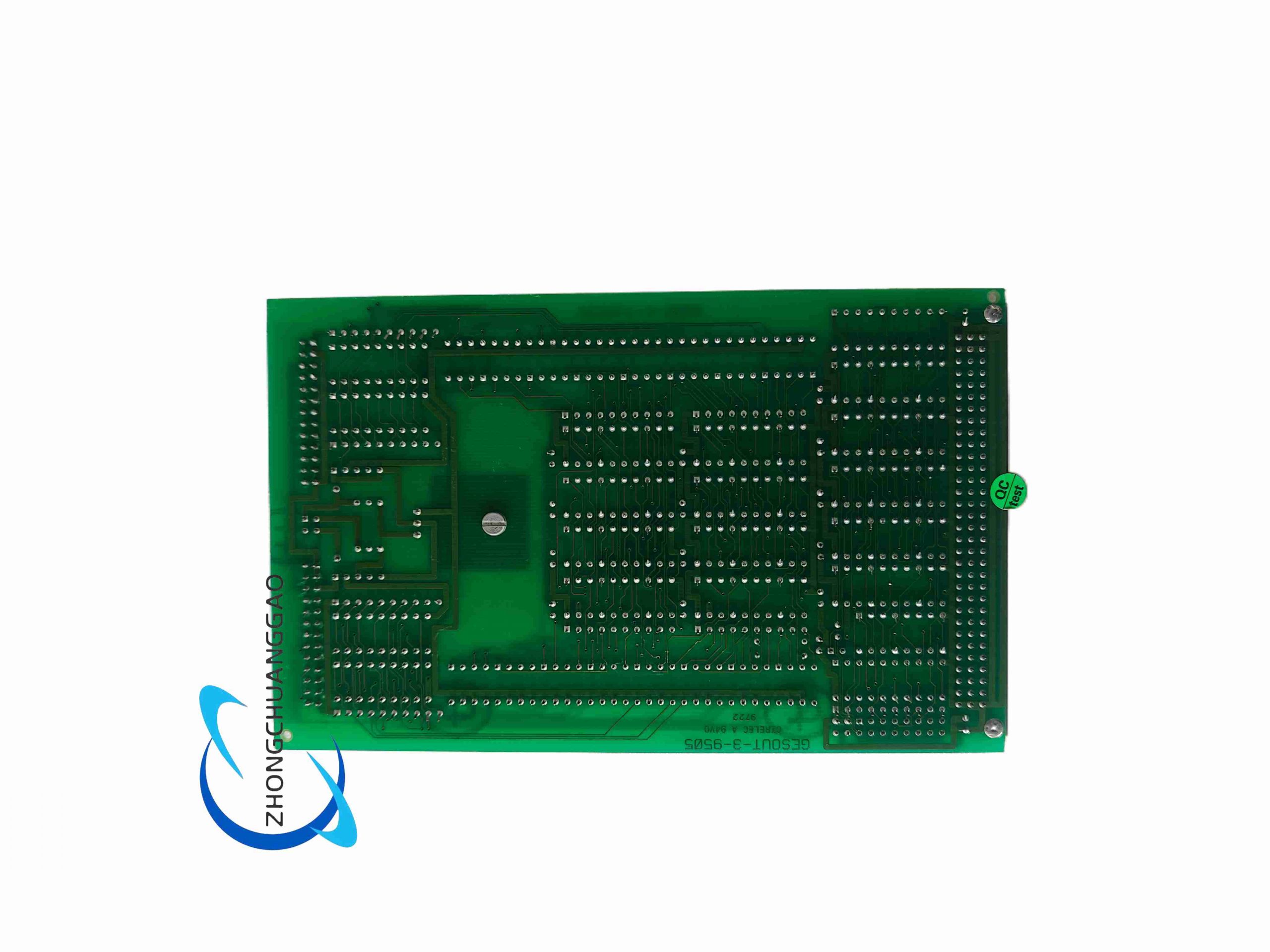
Material Composition: PCB with output drivers or relay elements; isolation components between logic and field sides; terminal blocks of flame-retardant plastic; metal or plastic module housing and mounting hardware; status LEDs and current-limiting resistors.
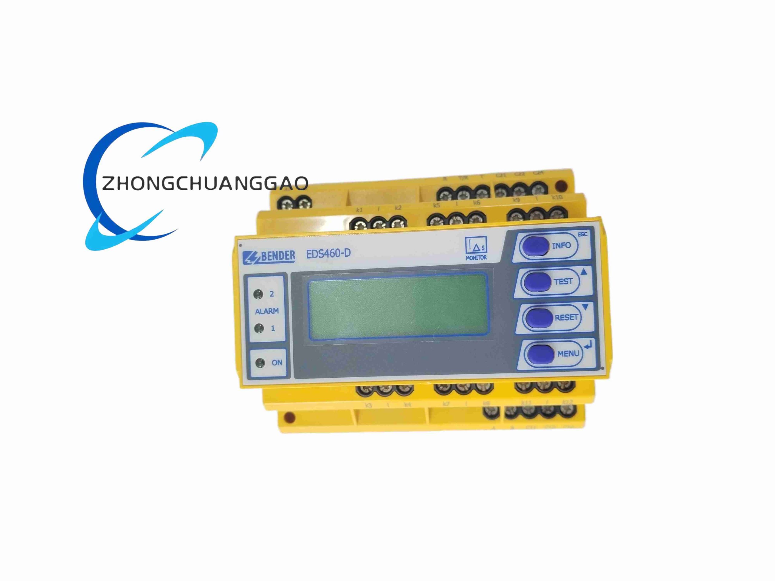
Structural Features: Front or top-accessible terminals numbered per channel; per-channel status indicators; module latch or screw fixing for retention on the backplane or DIN rail; keying and labeling for correct slot assignment; separation between field and logic wiring zones.
Working Principle: The host processor writes output values to the module over the internal bus. The output stage converts these values into contact closures, transistor switches, or proportional voltage/current signals that drive the connected field loads. Status feedback is returned to the host for monitoring and alarm generation.
Installation Requirements: Assign the module to the correct slot and configure the channel parameters in the host software before applying field power. Wire loads within the rated voltage and current, adding flywheel diodes for inductive loads. Observe polarity on transistor and analog outputs. Separate field wiring from logic wiring and use shielded cable where specified. Verify the total current drawn does not exceed the module and backplane ratings.
Precautions: Confirm whether each channel is relay, transistor, or analog before connecting loads. Do not exceed the rated load current or apply external voltage to an output not designed for it. Replace the module with power removed and the field circuit de-energized. Substitute OUT-3A for OUT-3 only after confirming functional equivalence in the system documentation. Keep a record of channel assignments and revisions.