Technical Specifications
|
Parameter
|
Specification
|
|
System supply
|
-24.5 V ±1.5 V DC, maximum 35 mA sensor supply
|
|
Eddy-current/Hall input
|
0 V to 26 V, reverse-polarity protected, 0-20 kHz
|
|
Magnetic VR input
|
1 Vpp minimum, 30 V RMS maximum, 0-20 kHz
|
|
Digital inputs
|
4 isolated channels, low 0-5 V, high 13-31 V
|
|
Current outputs
|
2 isolated channels, 0/4-20 mA or 20-4/0 mA, ±1 percent FS
|
|
Digital outputs
|
7 short-circuit-proof backplane outputs
|
|
Pulse outputs
|
3 open-collector channels, 31.2 V maximum, 16 mA maximum
|
|
Front pulse/sensor output
|
0-5 V TTL pulse, 0-3.9 V sensor factor output
|
|
USB interface
|
Type B configuration port
|
|
RS-485 interface
|
Up to 32 devices, 38400/57600/115200 baud
|
|
Profibus DP interface
|
Up to 31 devices, 12 Mbit/s maximum
|
|
Safety rating
|
Overspeed SIL 3, rotation direction SIL 2
|
|
Rack configuration
|
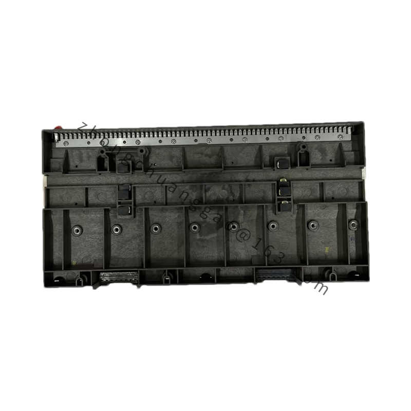
A6371 backplane, 19-inch 84HP, 3RU
|
Functional Features
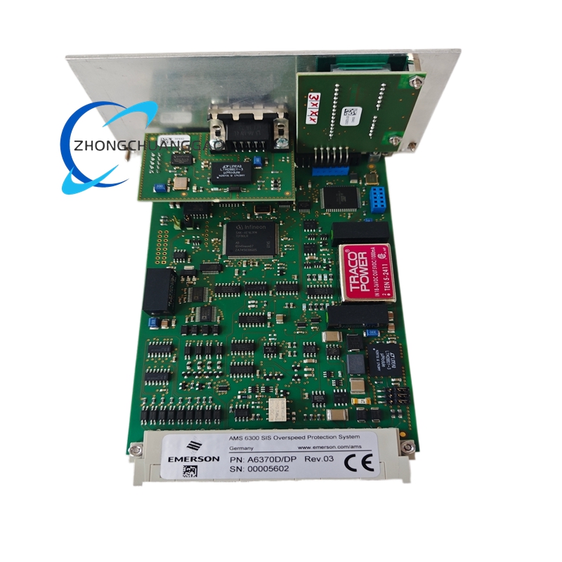
Supports eddy-current, Hall and magnetic velocity sensors. Provides speed, acceleration, direction and pulse reporting. Executes overspeed trip logic with SIL-rated reaction time. Transmits measurement data to AMS and host PLC systems through Profibus DP. Performs automatic self-test, channel-ok monitoring and fault latching.
Application Scenarios
Used in steam and gas turbines, generators, centrifugal and reciprocating compressors, boiler feed pumps, induced-draft fans, refinery rotating equipment, petrochemical compressors, cement kiln drives, mining mills and paper-machine prime movers.
Performance Parameters
Speed reaction time is shorter than measuring time plus 8 ms; at 3000 min⁻¹ in single-pulse mode typical reaction is 35 ms, in automatic mode approximately 12.5 ms. Direction reaction is shorter than three input periods plus 8 ms. Current output load is below 500 Ω. Operating temperature is -20 °C to 65 °C, storage -40 °C to 70 °C, humidity 5-95 percent non-condensing.
Material Composition
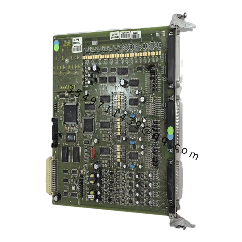
Industrial monitoring PCB with conformal-coated sections where required, metal rack mounting hardware with A6371 backplane, gold/lead-free connector contacts per Emerson manufacturing revision, and EMC-suppressed transceiver stages for RS-485/Profibus.
Structural Characteristics
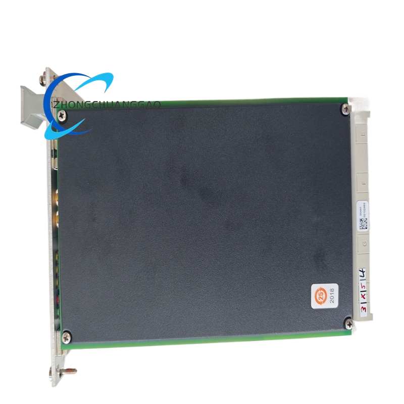
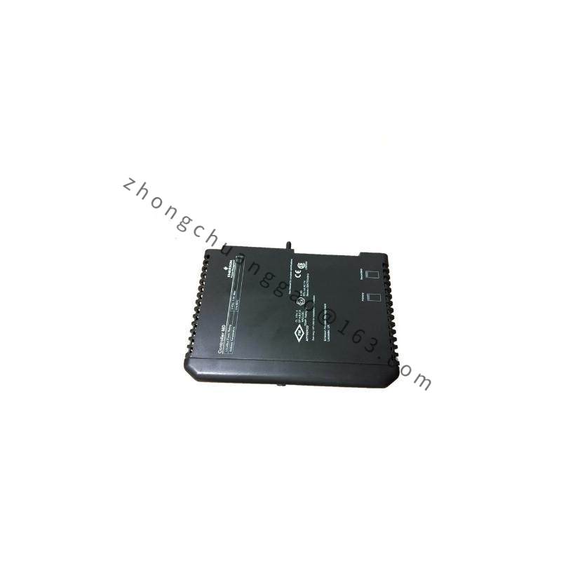
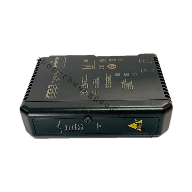
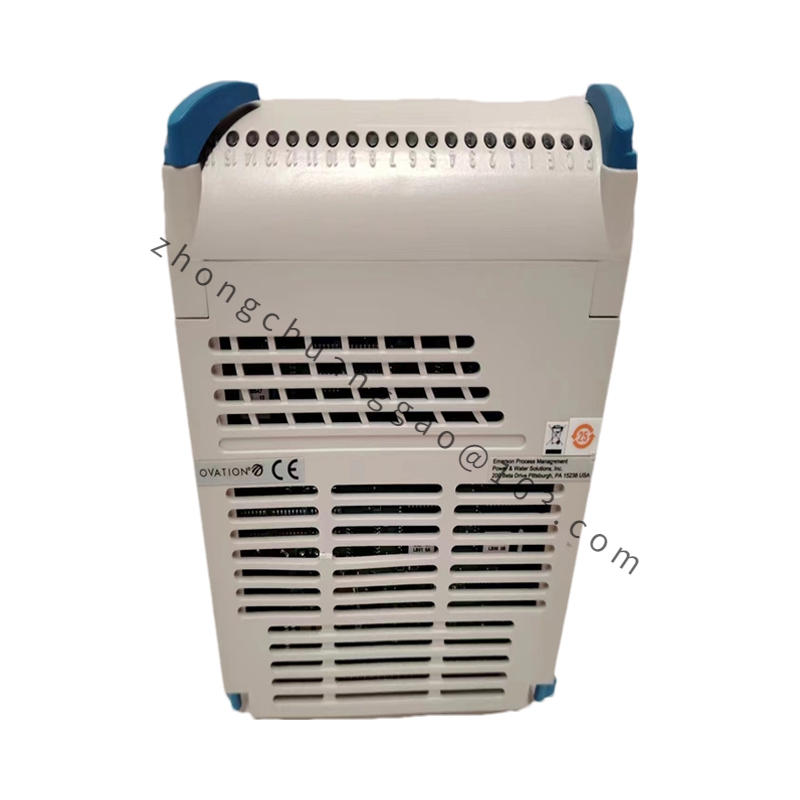
Plug-in monitor card for A6371 backplane, front USB-B and 9-pole Profibus DP connector, sensor input terminals on backplane, status LEDs for power/channel/ok/fault, short-circuit-proof pulse and sensor test jacks.
Working Principle
The monitor receives conditioned sensor signals from proximity, Hall or VR transducers, converts frequency and amplitude into speed and direction data, compares results with configured overspeed setpoints, and activates isolated digital, current and pulse outputs. Profibus DP reports measured values and diagnostics to the host controller without affecting the safety trip path.
Installation Requirements
Install the monitor in the A6371 backplane inside the specified 19-inch rack. Set Profibus address through Emerson configuration software and power-cycle after address change. Use approved A6363 Profibus cable, activate terminators at the first and last bus nodes, and接地 shield at one point. Match sensor type, supply voltage and input range before energizing.
Usage Precautions
Use only sensors compatible with eddy, Hall or VR input ranges. Verify SIL configuration, trip setpoints and latch/reset functions during commissioning. Do not bypass backplane digital inputs used for test, enable and reset. Perform periodic calibration of speed probes and verify Profibus termination to prevent bus communication errors.