Technical Specifications
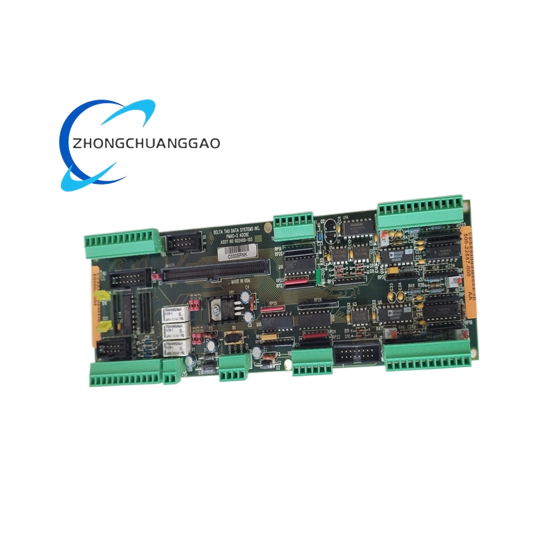
Analog output channels: four standard, eight in 602469-103 expanded configuration.
DAC resolution: 18-bit per channel.
Analog output range: -10 V to +10 V.
Analog output current: 10 mA maximum per channel.
Encoder input: quadrature A/B/Z, differential 5 V line receivers, single-ended supported by floating complementary lines.
Flag inputs: home, positive limit, negative limit, user, amplifier fault.
Flag isolation: optical isolation, 12 V to 24 V sink/source capable.
Amplifier enable: dry-contact relays, jumper-selectable NO/NC, sink/source.
Watchdog: relay output, jumper-selectable NO/NC.
Power supply: +15 V and -15 V, each below 200 mA; 5 V from PMAC-2 backplane or local TB.
Host interface: single PMAC-2 flat-cable/100-pin connection.
Functional Features
Per-channel 18-bit analog command for precision servo torque/velocity control.
Hardware clamp of analog outputs to 0 V on loss of +15 V, -15 V, +5 V, amplifier-enable loss, or PMAC watchdog trip.
Isolated amplifier-enable and flag circuits for safety separation from high-noise drive wiring.
Quadrature encoder decoding directly into PMAC-2 position registers.
Home, limit, user, and amplifier-fault flags processed through isolated opto inputs.
Optional ACC-8D isolator boards can be added when fully isolated encoder channels are required.
Application Scenarios
CNC machining centers.
Multi-axis servo retrofits.
Robotic joint control.
Semiconductor automation stages.
Test and inspection motion platforms.
UMAC/PMAC-2 rack-based closed-loop systems.
Performance Parameters
Analog command resolution: 18-bit across -10 V to +10 V.
Output settling and tracking governed by PMAC-2 servo loop and phase clock configuration.
Encoder support covers standard differential line-driver quadrature and indexed homing.
Analog output protection responds immediately to power loss, enable loss, or watchdog timeout.
Material Composition
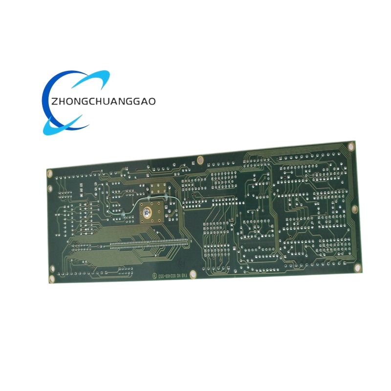
Industrial FR4 printed circuit board.
Optical isolators for flag and enable circuits.
Dry-contact electromechanical relays for amplifier enable and watchdog.
Gold or tin-plated connector contacts per PMAC-2 build standard.
Removable screw-terminal blocks and IDC headers.
Structural Characteristics
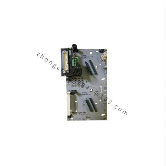
PMAC-2 accessory card format with flat-cable host connection.
Modular removable terminal blocks for machine wiring.
On-board 10-pin encoder headers for each axis group.
Jumper fields for enable relay mode, flag return, and 5 V encoder source selection.
Local ±15 V power terminal and optional local 5 V terminal for long encoder cables.
Working Principle
PMAC-2 computes servo position and velocity errors and sends digital command data to ACC-8E. The board’s DACs convert command values into isolated -10 V to +10 V analog signals for servo amplifiers. Encoders return A/B/Z quadrature to PMAC-2 through ACC-8E wiring; home, limit, user, and amplifier-fault signals pass through opto-isolated inputs. Amplifier-enable relays apply jumper-selected NO/NC logic, and the watchdog relay disconnects outputs when PMAC-2 communication or runtime health fails.
Installation Requirements
Power down PMAC-2 and remove ±15 V/5 V supplies before installing the board.
Seat the host flat-cable or backplane connector fully.
Configure amplifier-enable relays for NO or NC according to amplifier safety logic.
Provide isolated ±15 V bias power; keep PMAC-2 5 V separate unless local 5 V is intentionally selected.
Wire encoder complementary lines only for differential operation; leave them floating for single-ended operation.
Assign flag return voltage according to sinking or sourcing field devices.
Usage Precautions
Never energize analog outputs without confirming amplifier-enable logic.
Verify encoder 5 V current budget before using backplane 5 V; use local 5 V for long cable runs.
Do not mix isolated and non-isolated flag wiring on the same channel.
Confirm watchdog relay mode before automatic restart sequences.
Use shielded encoder cables with chassis-ground drain connection at one point.