Technical Specifications
Input voltage is 24 or 36 VAC. Output voltage is 0 to 20 VDC or 0 to 30 VDC depending on input tap. Output current range is 150 mA to 5.5 A DC. Horsepower coverage is approximately 1/50 to 1/8 HP with 0 to 20 VDC output and 1/25 to 1/4 HP with 0 to 30 VDC output. Speed regulation is 1% with armature feedback. Ambient operating temperature is -10°C to +45°C.
Functional Features
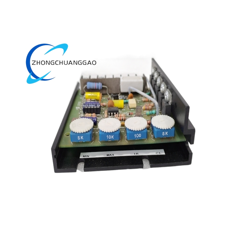
The control includes an inhibit circuit for start-stop operation, adjustable minimum and maximum speed, IR compensation, adjustable current limit, line voltage compensation, and acceleration setting. A 5K ohm speed potentiometer is used for manual control.
Application Scenarios
Use the control for office machinery, conveyors, packaging equipment, printers, process equipment, centrifuges, and exercise equipment with compatible low-voltage DC motors.
Structural Characteristics
The chassis format uses a barrier terminal strip for AC input, armature output, field output, speed pot, and inhibit connections. External heatsink may be required for higher-current 125-series models, but 123D-C rating is supported by the listed chassis configuration.
Working Principle
AC input is rectified to DC. The control varies armature voltage according to the speed command and feedback. Current-limit circuitry restricts motor torque during starting and overload. IR compensation offsets armature resistance drop to improve speed stability.
Installation Requirements
Mount where ambient temperature remains within -10°C to +45°C. Use the provided slot holes or chassis screws for fixed installation. Size all armature and AC wires per national and local electrical codes. Separate control wiring from motor power wiring in conduits or trays.
Usage Precautions
Do not exceed the 5.5 A DC output rating. Fuse the AC input at approximately 200% of full-load current for the 24 to 36 VAC version. Do not ground the speed-pot high terminal. Disconnect power before wiring or adjustment.