")
B&R X67AD0000
Product Introduction:
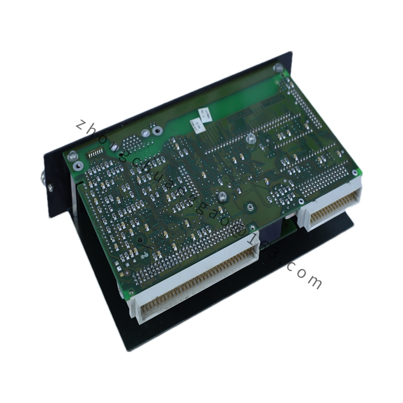
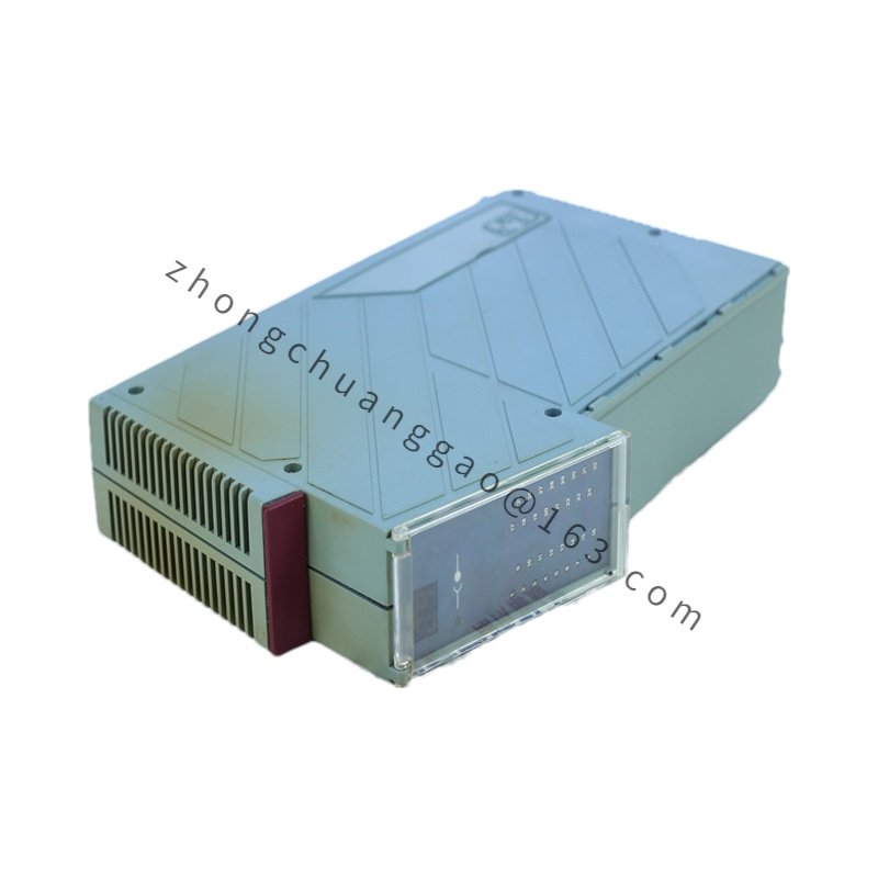
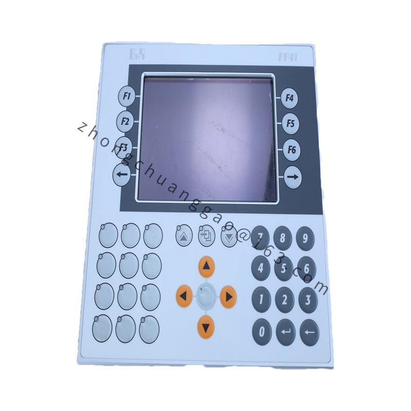
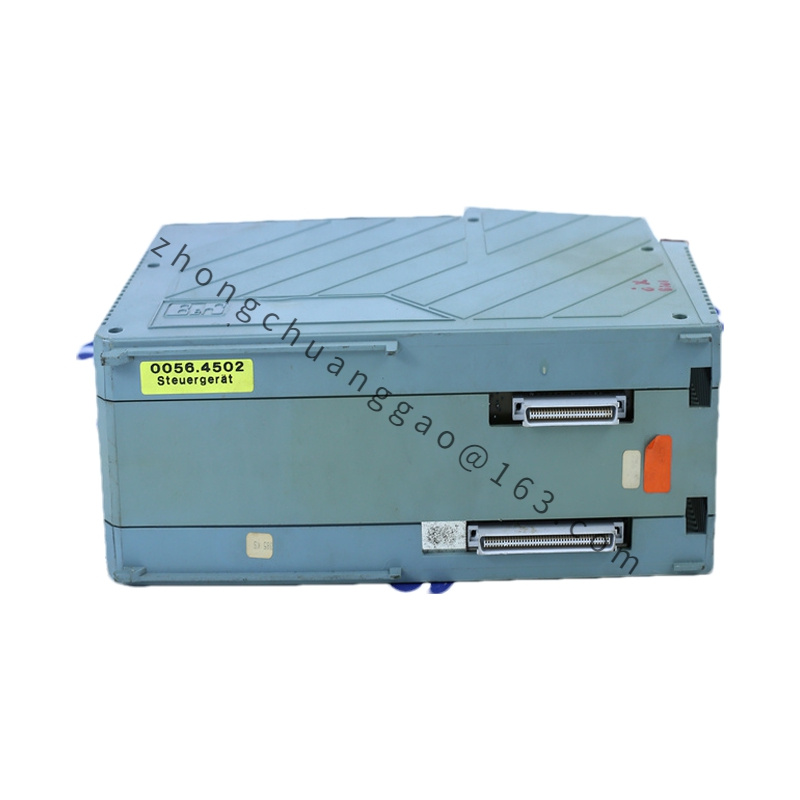
The B&R X67AD0000 is an 8-channel analog input module for the B&R X67 I/O system. It accepts both voltage and current signals with 16-bit resolution, making it a versatile module for acquiring analog process signals such as temperature, pressure, flow, and level from field transmitters. Each channel is individually configurable and electrically isolated.
Detailed content
Technical Specifications:
- Number of Channels: 8 (differential or single-ended)
- Input Type: Voltage: ±10 V, ±5 V, 0–10 V / Current: 0–20 mA, 4–20 mA
- Resolution: 16 bit (65,536 steps)
- Accuracy: ±0.1% of Full Scale (FS)
- Sample Rate: Up to 10 kS/s (aggregate, all channels)
- Isolation: Channel-to-channel galvanic isolation, 500 V DC
- Input Impedance (Voltage): > 1 MΩ
- Input Impedance (Current): 250 Ω (with internal burden resistor for 4–20 mA)
- Common Mode Rejection Ratio (CMRR): > 120 dB
- Supply Voltage (Bus): 24 V DC (from X67 bus)
- Operating Temperature: 0°C to +55°C
- Storage Temperature: -25°C to +70°C
- Dimensions (W x H x D): 72 mm x 90 mm x 115 mm
- Weight: Approx. 0.25 kg
Functional Features:
- 8 independently configurable analog input channels
- Selectable per channel: Voltage (±10 V, ±5 V, 0–10 V) or Current (0–20 mA, 4–20 mA)
- 16-bit A/D converter per channel with simultaneous sampling capability
- Channel-to-channel isolation (500 V DC) eliminates ground loop issues
- Diagnostic functions: Wire break detection, short-circuit detection, overrange detection per channel
- LED status indicators per channel (green = OK, red = fault)
- Software-configurable via B&R Automation Studio (range, scaling, filtering)
- Differential or single-ended input mode selectable per channel
Performance Parameters:
- Accuracy (at 25°C): ±0.1% FS
- Linearity Error: ±0.05% FS
- Temperature Drift: ±10 ppm/°C
- Settling Time: < 10 µs
- Noise (RMS): < 1 µV (voltage mode), < 10 nA (current mode)
- Power Consumption (Bus): < 2 W
- MTBF: > 100,000 hours (at 25°C)
Material Composition:
- Housing: Flame-retardant PA66 (polyamide 6.6) with glass fiber reinforcement
- Terminals: Tin-plated copper alloy with spring-cage connection
- PCB: FR-4 glass fiber epoxy laminate, conformally coated
- Isolation Barrier: Reinforced insulation, >500 V DC rating
- Connectors: Gold-plated pins for X67 bus connection
Structural Features:
- DIN rail mountable (TS 35, EN 60715)
- Front-facing X67 bus connector
- Spring-cage terminal connections for fast, tool-free wiring
- 8 LED indicators on front panel (one per channel)
- Module width: 72 mm (X67 standard width)
Working Principle:
The X67AD0000 receives analog signals from field transmitters via its 8 input channels. Each channel contains a 16-bit A/D converter that samples the analog input and converts it to a digital value. The input stage includes a programmable gain amplifier (PGA) and a multiplexer that allows selection of voltage or current range per channel. Channel-to-channel galvanic isolation is achieved through high-frequency transformer isolation or optical isolation barriers, ensuring that each channel operates independently with no cross-talk. The digital values are transmitted to the controller via the X67 bus using a cyclic data exchange protocol.
Advantages & Highlights:
- 8 channels with full isolation — ideal for multi-transmitter applications
- 16-bit resolution — excellent for precision measurement
- Voltage AND current input — one module replaces two separate modules
- Simultaneous sampling — all 8 channels sampled at the same instant
- Comprehensive diagnostics — wire break, short circuit, overrange per channel
- Wide input range selection — covers most standard transmitter signals
Applicable Industries:
- Process automation (chemical, petrochemical, pharmaceutical)
- Water and wastewater treatment
- Oil and gas monitoring
- Power generation
- HVAC and building automation
- Food and beverage processing
Installation Requirements:
- Mount on DIN rail TS 35 (EN 60715)
- Connect to X67 system bus via front-facing connector
- Use shielded twisted-pair cables for all analog inputs
- Ground the cable shield at the control cabinet end only (single-point grounding)
- For current inputs (4–20 mA), ensure loop supply ≥ 24 V DC
- For voltage inputs, use low-impedance sources (< 100 Ω source impedance)
- Do not exceed ±10 V on any voltage input channel
Usage Precautions:
- Do not apply voltage > ±10 V to any input channel (will damage the module)
- Do not leave current inputs open-circuit while powered (may cause erratic readings)
- Use shielded cables and ground at one end only
- Verify input range configuration in software before connecting field devices
- Do not mix voltage and current inputs on the same channel
- Ensure proper bus power (24 V DC, min. 2 A for X67 system)