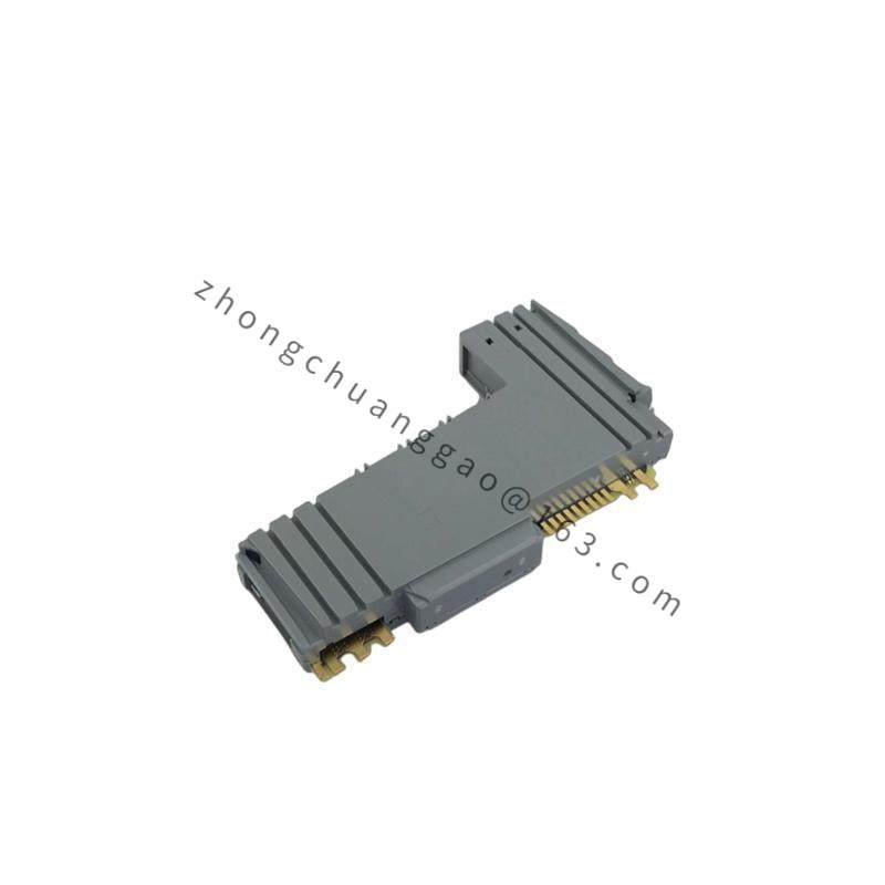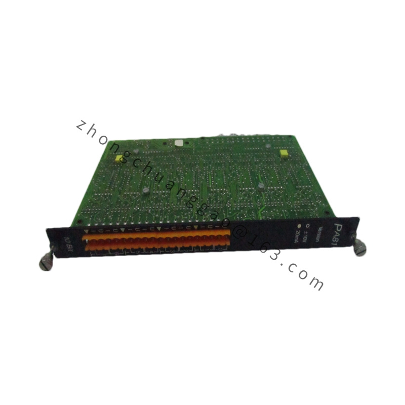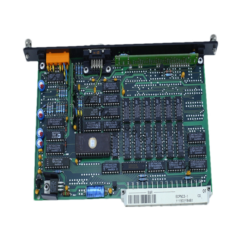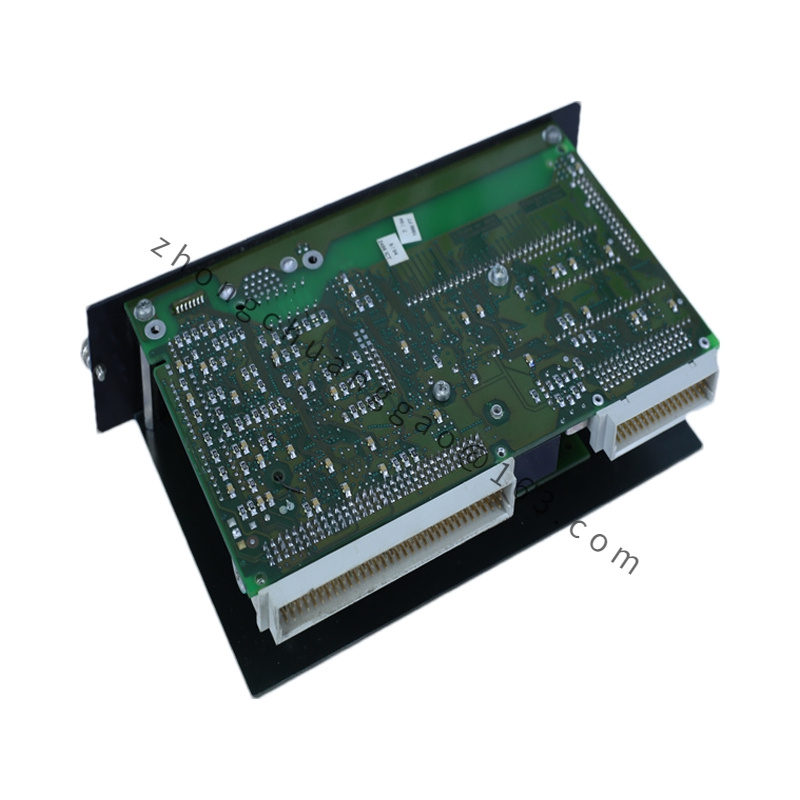
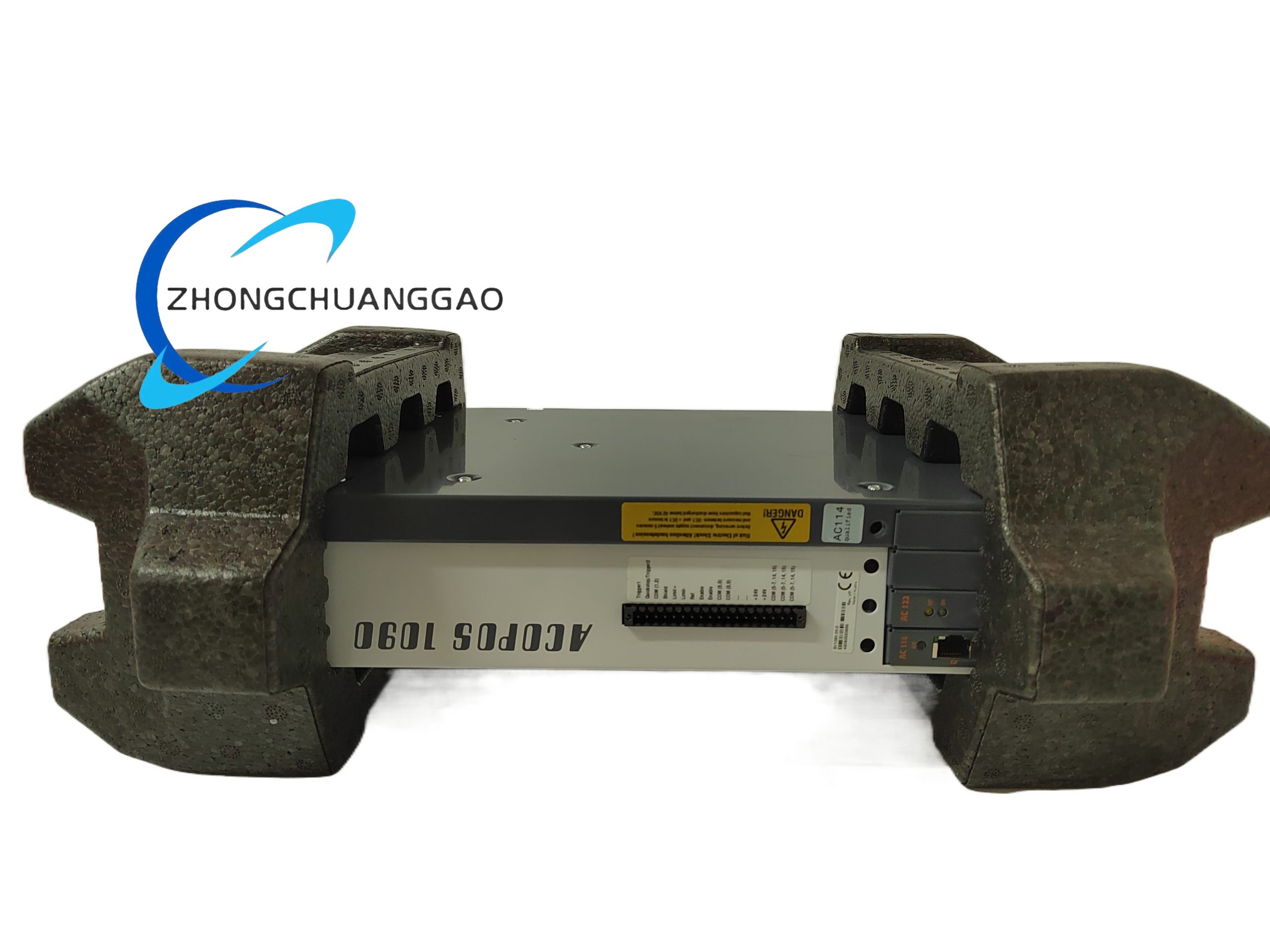

B&R X20HB2880
Product Series: B&R X20 Series (Accessories)
Product Introduction:
The B&R X20HB2880 is a 10-position terminal base designed for the B&R X20 compact I/O system. It provides screw-type terminal connections for field wiring to X20 modules (digital I/O, analog I/O, communication modules) that do not use M12 connectors directly. The terminal base mounts on a DIN rail and connects to the X20 backplane bus, enabling traditional wired field connections.
Detailed content
Technical Specifications:
| Parameter | Value |
|---|---|
| Product Type | Terminal base (passive distribution base) |
| Number of Positions | 10 |
| Compatible Modules | All X20 series I/O and communication modules with backplane connector |
| Terminal Type | Screw terminals, 2.5 mm² max wire cross-section |
| Wire Gauge | 22 AWG to 14 AWG (0.25 mm² to 2.5 mm²) |
| Tightening Torque | 0.5 Nm |
| Connector to Backplane | X20 backplane connector (bottom) |
| Supply Voltage | 24 VDC via backplane bus |
| Protection Class | IP20 |
| Operating Temperature | -25 °C to +70 °C |
| Storage Temperature | -40 °C to +85 °C |
| Dimensions (W × H × D) | 90 mm × 90 mm × 75 mm |
| Weight | ~120 g |
| Mounting | 35 mm DIN rail (TS 35, EN 60715) |
| Certifications | CE, UL, CSA |
Functional Features:
- 10 screw-type terminals for field device wiring (digital inputs, outputs, analog signals, power)
- Passive base — provides no active electronics; all signal processing occurs in the plugged-in X20 module
- Backplane bus connection — distributes 24 VDC power and communication signals to all mounted modules
- DIN rail mounting — standard 35 mm rail
- Terminal labeling strips included for wire identification
Structural Features:
- Housing: Polyamide (PA) + glass fiber reinforced (GF)
- Color: Light gray (RAL 7035)
- Screw terminals with captive clamps — prevents screw loss
- Backplane connector socket on the bottom
- Modular design — multiple X20HB2880 units can be placed side by side on the same DIN rail
Working Principle:
The X20HB2880 is a passive terminal distribution base. When an X20 module (e.g., X20DI9371, X20DO9332) is plugged into the base, the module’s backplane connector mates with the base’s socket. The 24 VDC power and digital/analog signals are transferred from the X20 backplane bus through the base to the module. Field devices are wired to the screw terminals on the front of the base, which are electrically connected to the corresponding module pins.
Advantages & Highlights:
- Traditional screw-terminal wiring — preferred in many installations over M12 connectors
- 10 positions — accommodates up to 10 single-channel or 5 dual-channel X20 modules
- Robust mechanical connection — screw terminals provide secure, vibration-resistant connections
- Cost-effective — lower cost than M12-equipped modules for simple applications
- Flexible labeling — clear wire identification
Applicable Industries:
- General industrial automation
- Machine building (OEM)
- Panel building
- Retrofit projects (replacing older terminal-based I/O)
- Standard machinery
Installation Requirements:
- Mount on 35 mm DIN rail (EN 60715)
- Maximum 10 modules per base (or combination fitting the 10 positions)
- Use stranded or solid copper wire, 0.25–2.5 mm²
- Tighten screws to 0.5 Nm
- Ensure no wire strands protrude beyond the terminal clamp
Usage Precautions:
- Do not exceed 2.5 mm² wire cross-section — larger wires will not fit or may damage the terminal
- Strip wire to exactly 8–10 mm — too short = poor contact, too long = risk of short circuit
- Do not mix different module types without verifying pin compatibility in the hardware configuration
- Ensure proper torque — undertightening causes poor contact; overtightening damages the terminal