
Product Series: B&R X20 Series (Compact I/O System)
Product Introduction:
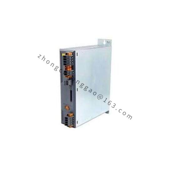
The B&R X20DO9332 is an 8-channel digital output module in sink (NPN) configuration from the B&R X20 compact I/O system. It provides 8 sink outputs at 24 VDC, 0.5 A per channel, switching the load to ground. This is the counterpart to the X20DC2398 and is designed for applications requiring NPN/sink-type switching, which is the standard in European industrial automation.
Technical Specifications:
| Parameter | Value |
|---|---|
| Number of Channels | 8 digital outputs |
| Output Type | Sink (NPN) |
| Output Voltage | 24 VDC |
| Output Current per Channel | 0.5 A |
| Total Output Current | 4 A (aggregate) |
| Logic Level “1” | 24 VDC (output active — sink closed) |
| Logic Level “0” | 0 V (output inactive — sink open) |
| Switching Frequency | Up to 10 kHz |
| Response Time (ON→OFF / OFF→ON) | ≤ 1 ms |
| Isolation Voltage | 500 V DC (channel to channel, channel to backplane) |
| Protection Class | IP20 (front side), IP67 (when mated with M12 connector) |
| Connector Type | M12, 8-pin, A-coded |
| Supply Voltage | 24 VDC via backplane bus |
| Power Consumption (max) | ~2.5 W |
| Operating Temperature | -25 °C to +70 °C |
| Storage Temperature | -40 °C to +85 °C |
| Relative Humidity | 5 % to 95 % (non-condensing) |
| Dimensions (W × H × D) | 25 mm × 90 mm × 75 mm |
| Weight | ~85 g |
| Certifications | CE, UL, CSA, ATEX (Zone 2) |
Functional Features:
Structural Features:
Working Principle:
Each output channel uses an NPN Darlington transistor or MOSFET in sink configuration. The controller sends a logic “1” via the backplane → the NPN transistor turns ON → the output terminal is connected to GND (0 V) → current flows from the external +24 VDC supply, through the load, into the output terminal, and to GND. Logic “0” turns the transistor OFF, opening the circuit.
Advantages & Highlights:
Applicable Industries:
Installation Requirements:
Usage Precautions: