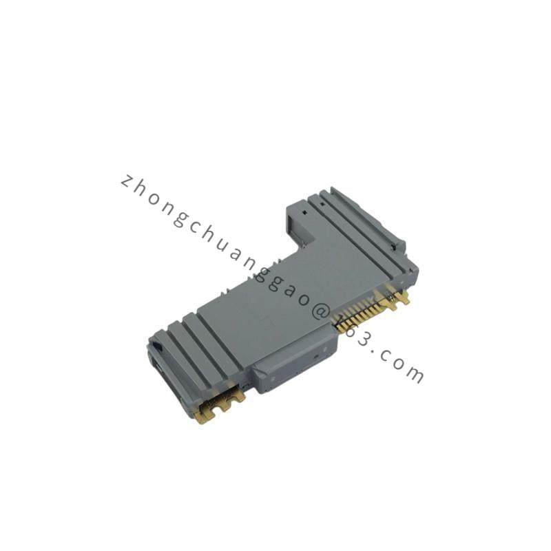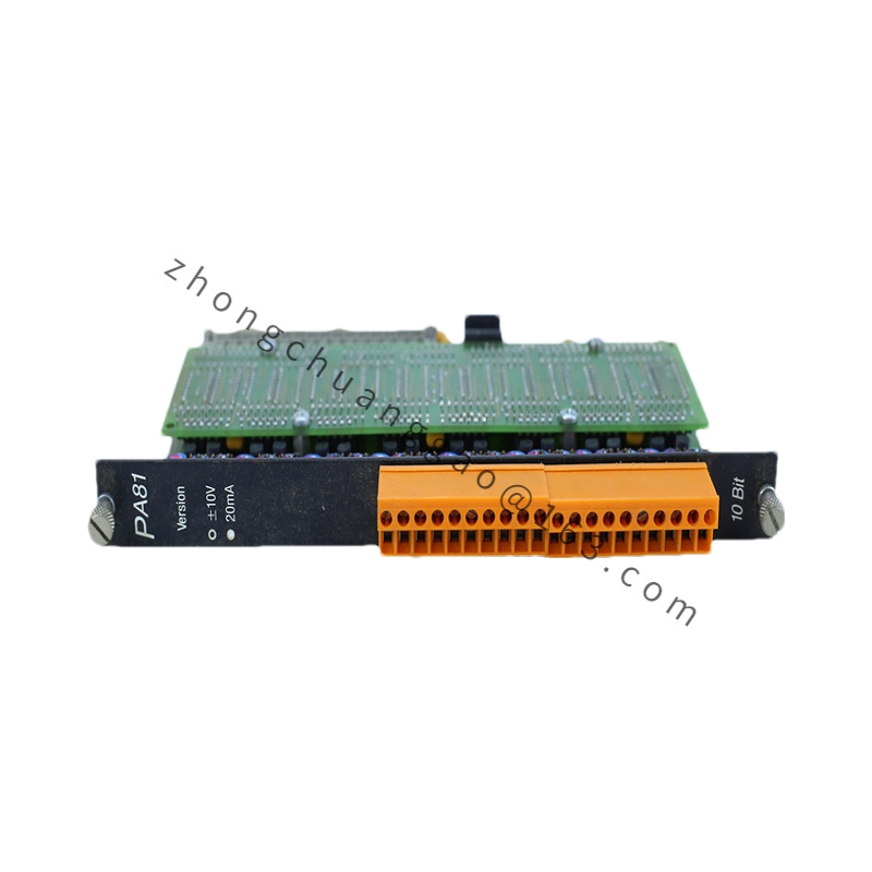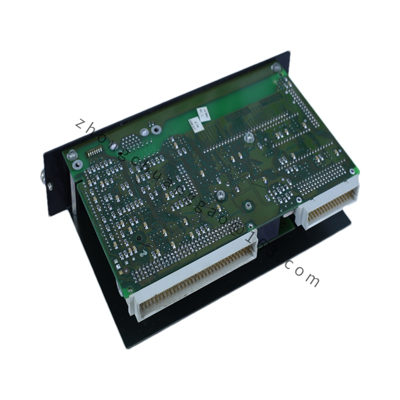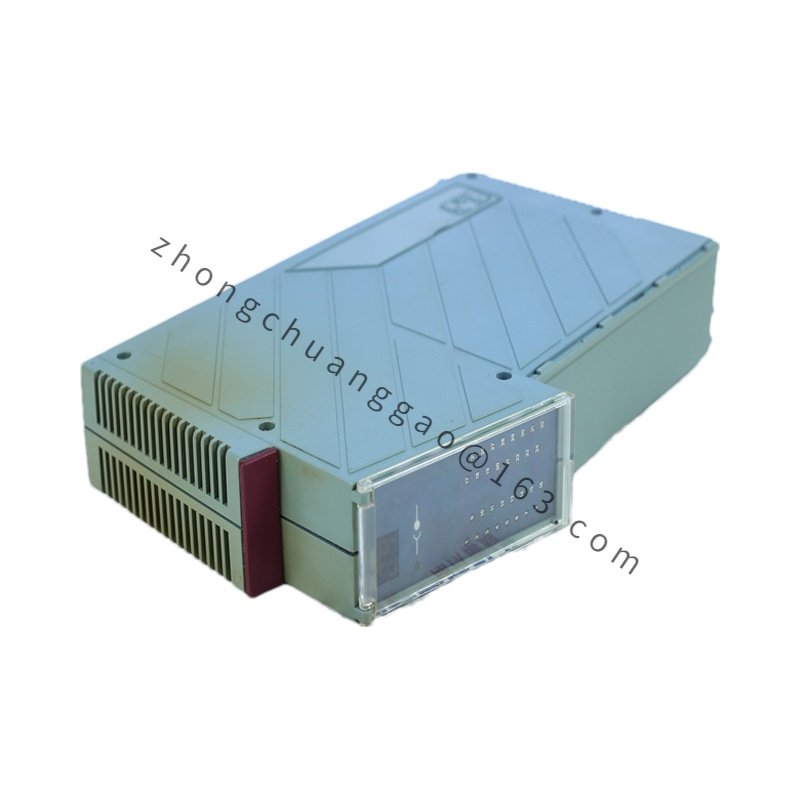
B&R X20AT2402
Product Type: 2-Channel Analog Input Module (Current/Voltage/Resistance/Thermocouple)
Product Introduction:
The B&R X20AT2402 is a 2-channel universal analog input module for the B&R X20 distributed I/O system. It accepts four different input signal types: 0-20mA, 4-20mA current, 0-10V voltage, 0-100Ω to 1000Ω resistance (RTD/PTC), and thermocouple (Type J, K, T, N, S, R, B, E). Each channel features 16-bit resolution with configurable filtering for noise rejection in industrial environments.
Detailed content
Technical Specifications:
| Parameter | Value |
|---|---|
| Number of Channels | 2 independent channels |
| Input Signal Types | 0-20mA, 4-20mA, 0-10V, RTD (Pt100, Pt1000, Ni100, Ni1000), Thermocouple (J, K, T, N, S, R, B, E) |
| Resolution | 16-bit (65,536 steps) |
| Input Accuracy (Current/Voltage) | ±0.1% of full scale (typical), ±0.2% (max) |
| Input Accuracy (RTD) | ±0.3°C (Pt100, 0°C to 100°C) |
| Input Accuracy (Thermocouple) | ±1.5°C (Type K, 0°C to 500°C) |
| Update Rate | ≤ 10 kHz (both channels simultaneously) |
| Input Impedance (Voltage) | ≥ 1 MΩ |
| Input Impedance (Current) | ≤ 50Ω (burden voltage ≤ 2V at 20mA) |
| Cold Junction Compensation (TC) | Integrated, ±0.5°C accuracy |
| Isolation Voltage | 500V DC (channel-to-channel, channel-to-bus) |
| X20 Bus Interface | X20 system bus (up to 63 modules) |
| Supply Voltage | 24V DC (via X20 bus) |
| Power Consumption | ≤ 1.5W (typical) |
| Operation Temperature | -25°C to +70°C |
| Protection Class | IP20 (front), IP65 (with cover) |
| Dimensions (W×H×D) | 22.5 mm × 90 mm × 120 mm |
| Weight | Approx. 140 g |
| Conformity | CE, UL, CSA, ATEX Zone 2 |
Functional Features:
- Two universal input channels — each channel independently configurable for current, voltage, RTD, or thermocouple
- 16-bit ADC resolution — 65,536 discrete steps for high-precision measurement
- Configurable digital filter per channel: 0.1 ms, 0.5 ms, 1 ms, 5 ms, 10 ms, 50 ms, 100 ms, 500 ms — rejects noise while maintaining response speed
- Cold junction compensation (CJC) built into the module for thermocouple inputs — no external CJC sensor required
- RTD excitation current programmable: 0.1 mA, 0.5 mA, 1.0 mA — selectable to minimize self-heating error
- Diagnostic per channel: overrange detection, underrange detection, open-wire detection (for RTD/TC), short-circuit detection
- LED indicators per channel: power, fault, input active
Structural Characteristics:
- Snap-in DIN rail TS35 mounting
- Spring-loaded push-in terminals for 0.14 mm² to 2.5 mm² wire
- Housing: glass-fiber reinforced polyamide (PA66-GF30)
- Two input connectors on the front, each with dedicated LED status indicator
- Rear X20 bus connector
Working Principle:
Each channel contains a 16-bit Sigma-Delta ADC with a programmable gain amplifier (PGA). For current inputs, the signal current flows through a precision shunt resistor (250Ω for 0-20mA → 0-5V, 500Ω for 4-20mA → 2-10V), and the resulting voltage is digitized. For voltage inputs, the signal is attenuated/amplified by the PGA to match the ADC input range. For RTD inputs, the module sources a programmable excitation current through the RTD and measures the resulting voltage drop — resistance is calculated via R = V/I. For thermocouple inputs, the microvolt-level signal is amplified by a high-gain, low-offset instrumentation amplifier, and the cold junction temperature (measured by an integrated sensor) is added to compute the true thermocouple temperature using NIST polynomial lookup tables stored in the module’s memory. The digital filter averages multiple samples over the configured time window to reject noise.
Advantages & Highlights:
- Universal input per channel — one module replaces four separate modules (current, voltage, RTD, TC)
- 16-bit resolution (65,536 steps) — exceptional precision for process measurement
- Integrated cold junction compensation — eliminates need for external CJC sensor on thermocouple inputs
- Configurable RTD excitation current — minimizes self-heating error on precision RTDs
- 8-level digital filter — flexible noise rejection from 0.1 ms (fast response) to 500 ms (maximum noise rejection)
- Full galvanic isolation (500V DC) — each channel isolated from every other channel and from the bus
Applicable Industries:
- Process automation (temperature, pressure, flow, level measurement)
- HVAC (temperature monitoring with Pt100/thermocouple)
- Food and beverage (temperature control with thermocouple)
- Plastics and rubber (RTD temperature measurement)
- Power generation (thermocouple monitoring)
- Pharmaceutical (precision temperature with Pt1000)
Installation Requirements:
- Mount on DIN rail TS35 near the sensor for short cable runs
- Use shielded twisted-pair cable for all input signals
- Maximum cable length: 50 m (current/voltage), 10 m (RTD — 3-wire or 4-wire), 10 m (thermocouple — use correct TC extension wire type)
- For RTD: use 3-wire or 4-wire connection to eliminate lead resistance error
- For thermocouple: use correct thermocouple extension wire (e.g., Type K extension wire for Type K TC) — using wrong wire type causes large measurement errors
- Connect 24V DC bus power from the X20 bus coupler
Usage Precautions:
- Do not apply voltages exceeding 30V DC to current/voltage input channels — this destroys the input stage
- Do not apply voltages exceeding 10V DC to RTD/thermocouple channels — this damages the low-voltage input amplifier
- For RTD inputs: always use 3-wire or 4-wire connection — 2-wire connection includes lead resistance in the measurement, causing error
- For thermocouple inputs: match the thermocouple type exactly in the configuration — wrong type causes errors of 100°C or more
- Set the correct filter time — too short a filter allows noise; too long a filter slows response to real process changes
- Do not disconnect an RTD or TC while the module is powered — open-wire detection will flag a fault, and the measured value becomes invalid