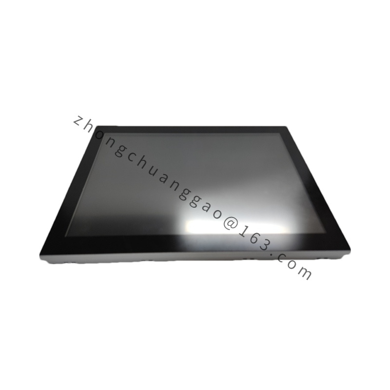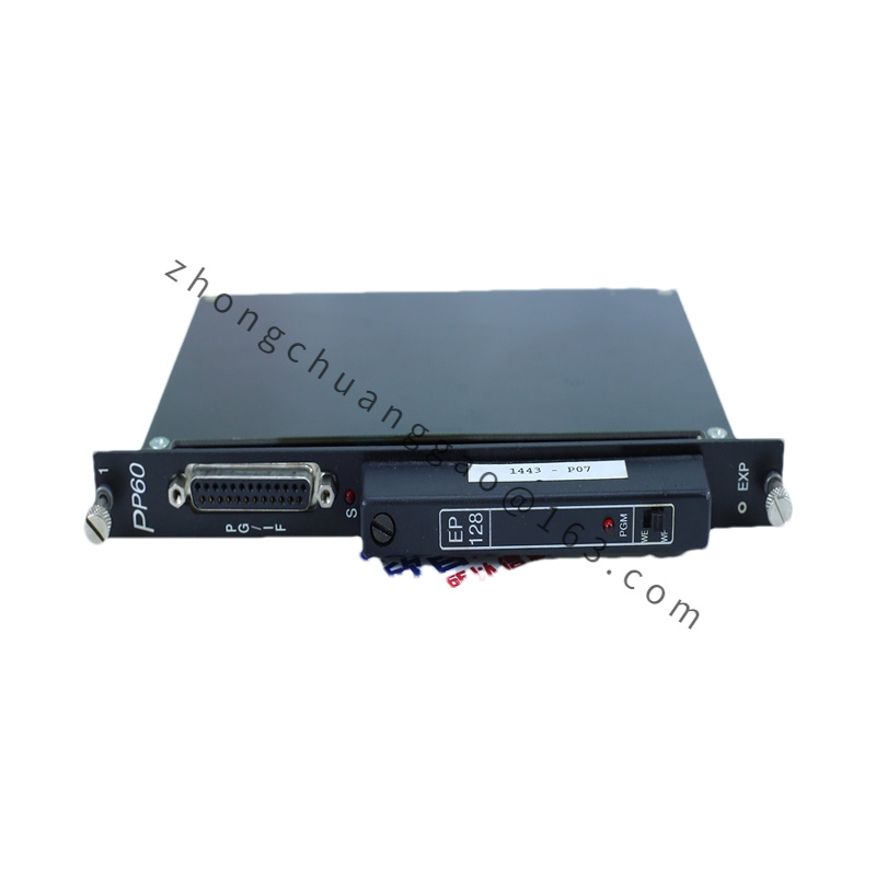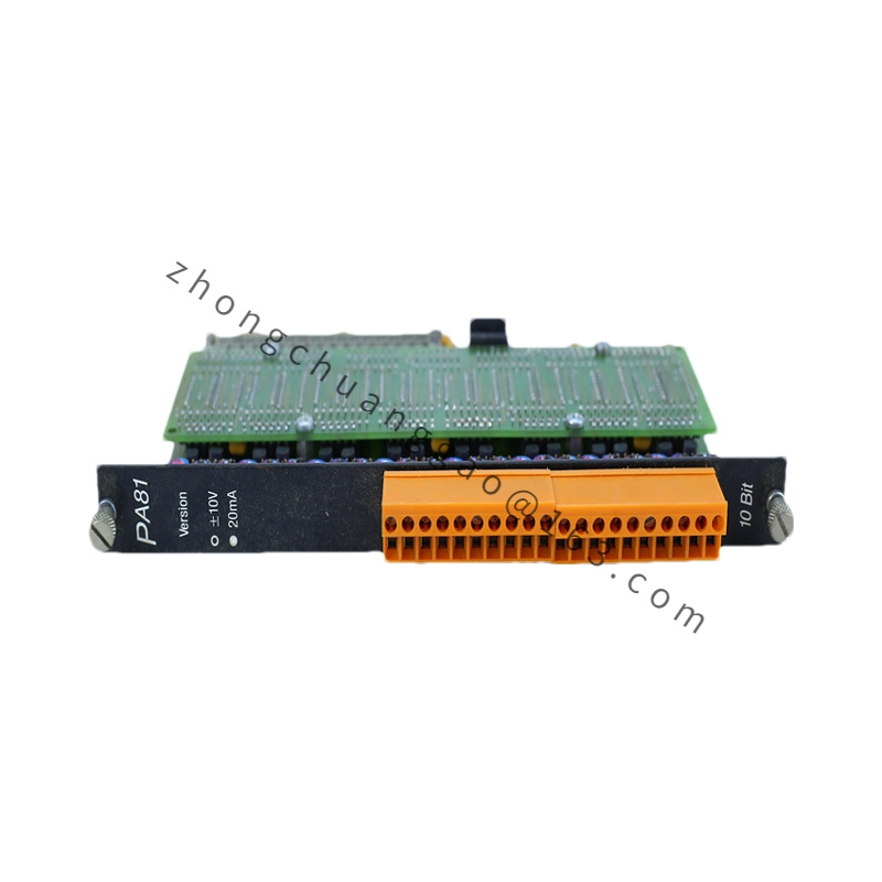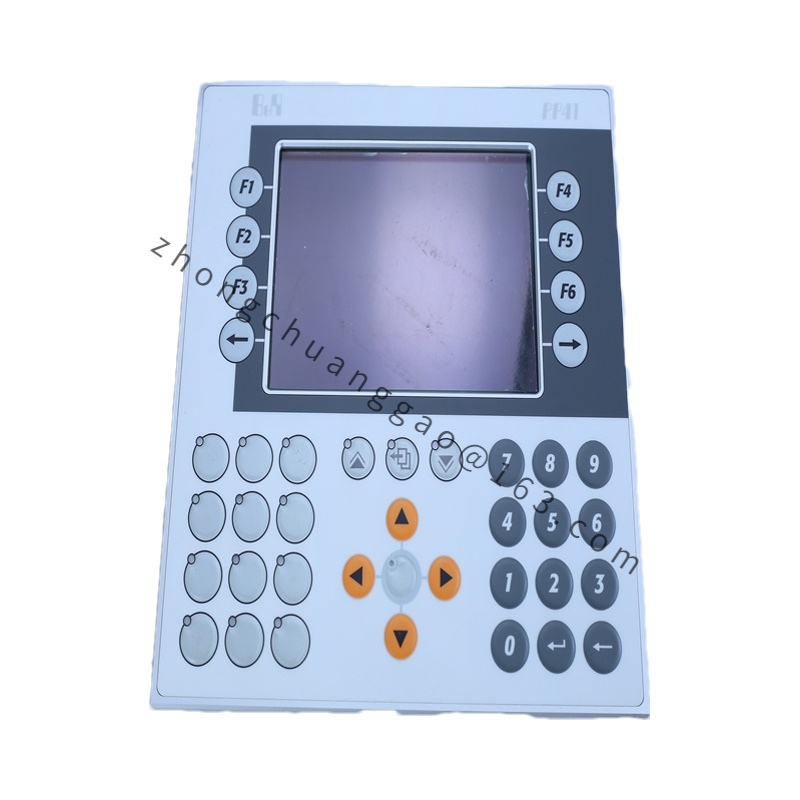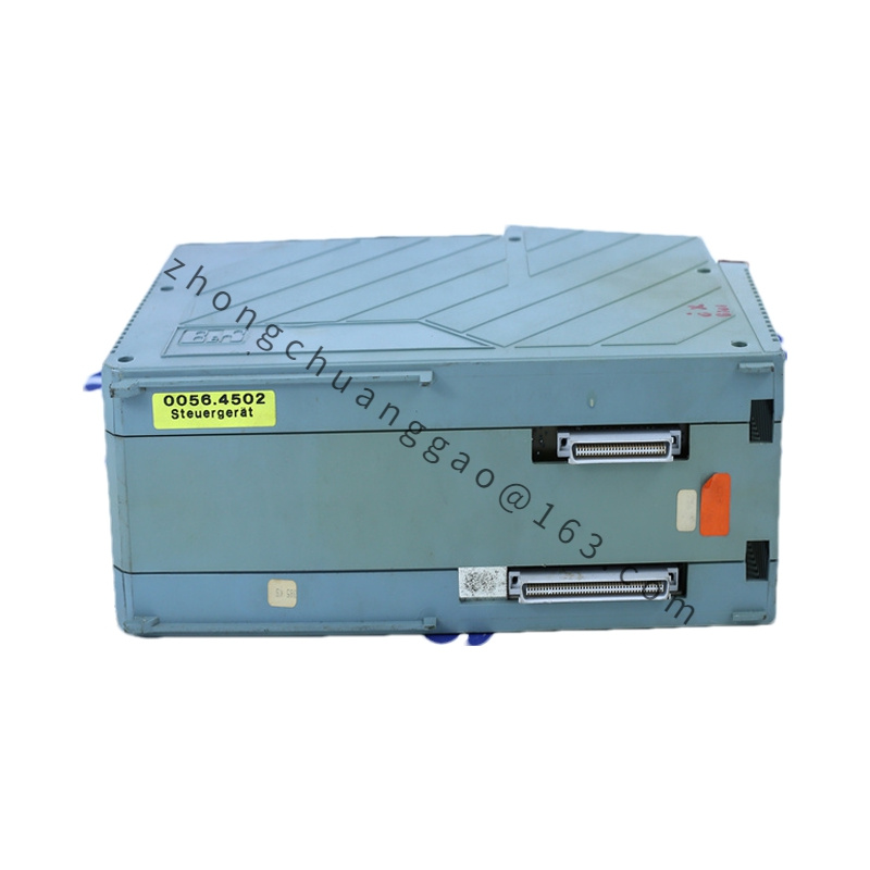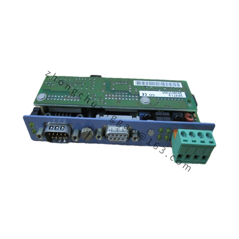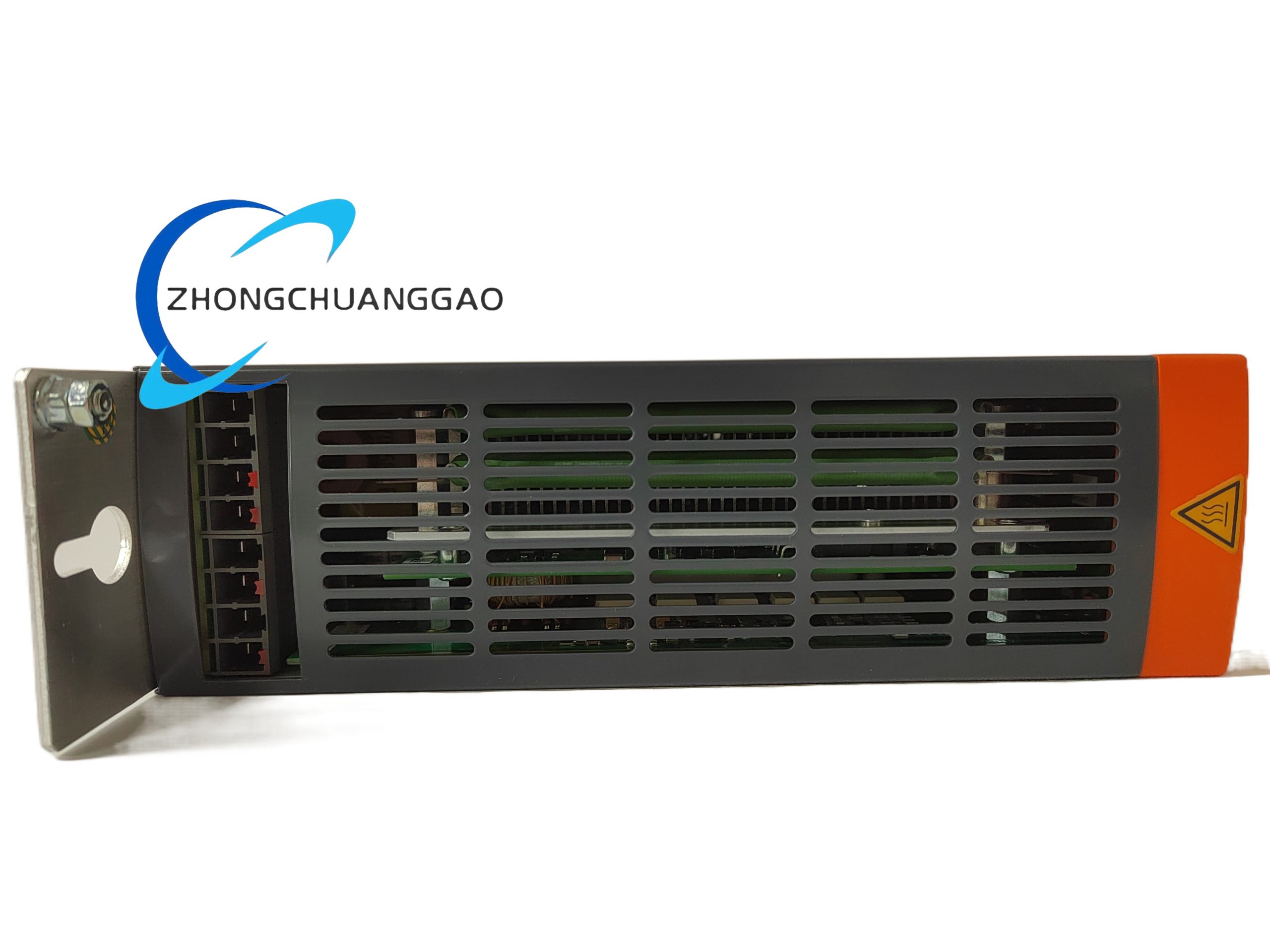
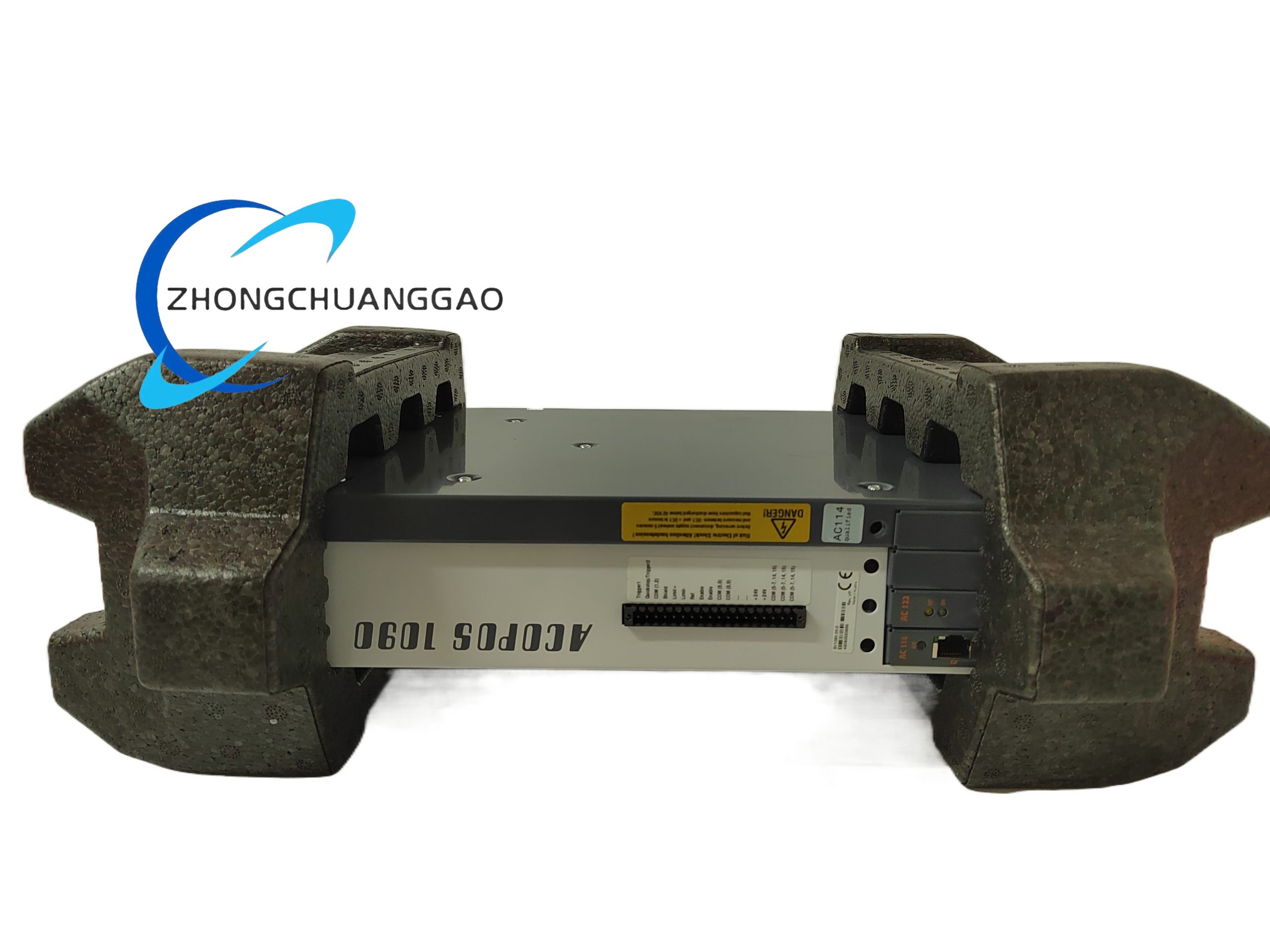
B&R X20AO4622
Product Introduction:
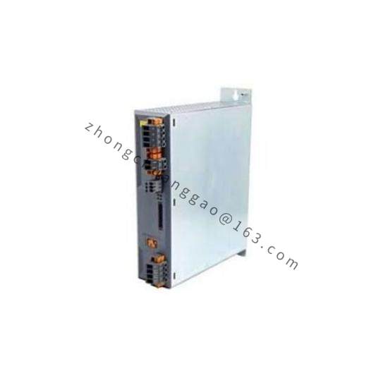
The B&R X20AO4622 is a 4-channel analog output module for the B&R X20 distributed I/O system. It provides four independently configurable analog output channels that can be set to output either 0-20mA / 4-20mA current or 0-10V voltage signals. Each channel features 16-bit resolution, ensuring precise control of actuators such as control valves, variable frequency drives (VFDs), and proportional amplifiers.
Detailed content
Technical Specifications:
| Parameter | Value |
|---|---|
| Number of Channels | 4 independent channels |
| Output Signal Types | 0-20mA, 4-20mA (current) / 0-10V (voltage) |
| Resolution | 16-bit (65,536 steps) |
| Output Accuracy | ±0.1% of full scale (typical), ±0.2% (max) |
| Update Rate | ≤ 10 kHz (all channels simultaneously) |
| Output Impedance (Current) | ≤ 100Ω (0-20mA), ≤ 500Ω (4-20mA) |
| Output Impedance (Voltage) | ≤ 10Ω |
| Load Capacity (Current) | ≤ 500Ω (0-20mA), ≤ 250Ω (4-20mA) |
| Load Capacity (Voltage) | ≥ 2 kΩ (minimum load) |
| Isolation Voltage | 500V DC (channel-to-channel, channel-to-bus) |
| X20 Bus Interface | X20 system bus (up to 63 modules) |
| Supply Voltage | 24V DC (via X20 bus) |
| Power Consumption | ≤ 2.5W (typical) |
| Operation Temperature | -25°C to +70°C |
| Protection Class | IP20 (front), IP65 (with cover) |
| Dimensions (W×H×D) | 22.5 mm × 90 mm × 120 mm |
| Weight | Approx. 150 g |
| Conformity | CE, UL, CSA, ATEX Zone 2 |
Functional Features:
- Four independently configurable channels — each can be set to current or voltage output independently
- 16-bit DAC resolution — 65,536 discrete steps for ultra-fine control
- Simultaneous update of all 4 channels at up to 10 kHz — critical for multi-axis synchronized control
- Linearization table — 16-point piecewise linearization per channel for non-linear actuator compensation
- Diagnostic per channel: overcurrent detection, open-loop detection, short-circuit detection
- LED indicators per channel for status monitoring (power, fault, output active)
- Galvanic isolation between all channels and the bus — eliminates ground loop issues
Structural Characteristics:
- Snap-in DIN rail TS35 mounting
- Spring-loaded push-in terminals for 0.14 mm² to 2.5 mm² wire
- Housing: glass-fiber reinforced polyamide (PA66-GF30)
- Four output connectors on the front, each with dedicated LED
- Rear X20 bus connector
Working Principle:
Each channel contains a 16-bit Digital-to-Analog Converter (DAC) that converts the digital value from the X20 bus into an analog voltage. For current output mode, this voltage drives a precision current loop circuit (Howland pump or transistor-based) that forces a proportional current through the load regardless of load resistance (within compliance limits). For voltage output mode, the DAC output is buffered by a low-impedance operational amplifier. The 16-point linearization table stored in the module’s memory corrects for DAC non-linearity and actuator non-linearity (e.g., equal-percentage valve characteristic). All four channels are updated simultaneously via a shared update trigger from the bus master.
Advantages & Highlights:
- 16-bit resolution (65,536 steps) — far superior to 12-bit modules (4,096 steps) for precision applications
- 10 kHz simultaneous update — all 4 channels change at exactly the same instant, essential for synchronized valve/drive control
- Per-channel current OR voltage — mix current and voltage outputs on the same module (e.g., 2× 4-20mA + 2× 0-10V)
- 16-point linearization — compensates for non-linear actuators without burden on the controller
- Full galvanic isolation — each channel is isolated from every other channel and from the bus
Applicable Industries:
- Process automation (control valve positioning: 4-20mA to I/P transducers)
- Variable frequency drive speed control (0-10V to VFD)
- Hydraulic proportional valve control
- Temperature control (0-10V to heater SSR)
- Batch dosing and mixing
- HVAC damper and valve control
Installation Requirements:
- Mount on DIN rail TS35 near the field devices for short analog cable runs
- Use shielded twisted-pair cable for current outputs (4-20mA); shielded coaxial or twisted-pair for voltage outputs (0-10V)
- Maximum cable length: 50 m (current, 4-20mA), 20 m (voltage, 0-10V) — longer runs require shielded cable with driven shield
- For current output: ensure total loop resistance (wire + load) ≤ 500Ω (4-20mA) or ≤ 250Ω (0-20mA)
- Connect 24V DC bus power from the X20 bus coupler
Usage Precautions:
- Do not exceed 500Ω total loop resistance on current outputs — the module cannot maintain current above compliance voltage
- Do not short-circuit voltage outputs — this can damage the output amplifier
- Do not leave voltage outputs unloaded (below 2 kΩ) — this causes instability and oscillation
- Set the correct output range (0-20mA vs 4-20mA) in the configuration — wrong range causes 25% offset error
- Enable linearization only when needed — incorrect linearization table causes output errors