B&R MCNT33-0
Product Introduction:
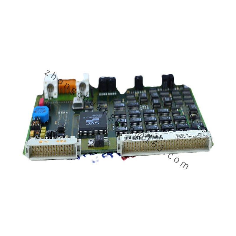
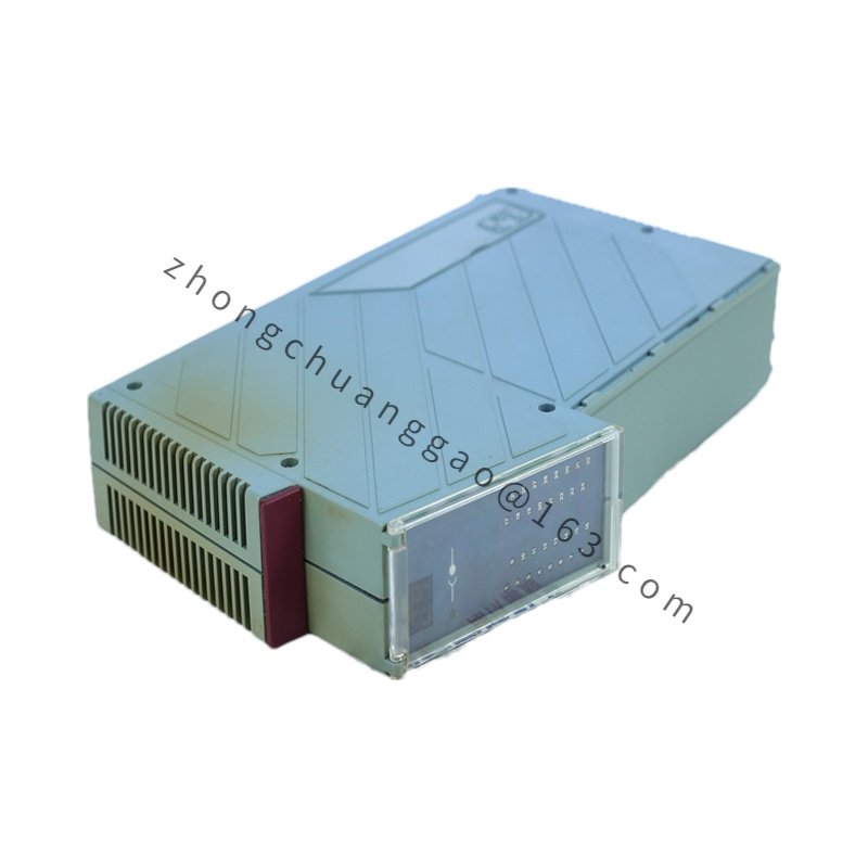
The B&R MCNT33-0 is a 3-channel high-speed counter module for the B&R X20 distributed I/O system. It is designed for precise frequency measurement, pulse counting, and encoder evaluation in motion control and process automation applications. Each of the three channels supports input frequencies up to 500 kHz, making it suitable for high-speed encoder interfaces and tachometer signals.
Detailed content
Technical Specifications:
| Parameter | Value |
|---|---|
| Number of Counter Channels | 3 independent channels |
| Maximum Input Frequency | 500 kHz per channel |
| Counter Resolution | 32-bit (±2,147,483,647 counts) |
| Counter Modes | Up-counting, Down-counting, Up/Down counting, Frequency measurement, Period measurement, Gate function |
| Input Signal Types | NPN, PNP, Push-Pull (TTL), Differential (RS-422) |
| Input Voltage (NPN/PNP) | 10V to 30V DC |
| Input Voltage (TTL) | 5V DC (high: ≥ 3.5V, low: ≤ 1.5V) |
| Input Impedance (Differential) | 100Ω (terminated), 220Ω (unterminated) |
| Isolation Voltage | 500V DC (channel-to-channel, channel-to-bus) |
| X20 Bus Interface | X20 system bus (up to 63 modules) |
| Supply Voltage | 24V DC (via X20 bus) |
| Operation Temperature | -25°C to +70°C |
| Protection Class | IP20 (front), IP65 (with cover) |
| Dimensions (W×H×D) | 22.5 mm × 90 mm × 120 mm |
| Weight | Approx. 160 g |
| Conformity | CE, UL, CSA, ATEX Zone 2 |
Functional Features:
- 3 independent 32-bit counters — can count 3 separate encoder signals simultaneously
- Frequency measurement mode — measures input frequency from 0.1 Hz to 500 kHz with 0.01% accuracy
- Period measurement mode — measures signal period for speed calculation
- Gate function — enables counting only during a specified time window
- Hardware-based counting — all counting is done in hardware, independent of the bus cycle — zero CPU load
- Differential input support — noise-immune RS-422 interface for long cable runs (up to 100 m)
- Zero-crossing detection for AC tachometer signals (with external conditioning)
Structural Characteristics:
- Snap-in DIN rail TS35 mounting
- Spring-loaded push-in terminals for 0.14 mm² to 2.5 mm² wire
- Housing: glass-fiber reinforced polyamide (PA66-GF30)
- Three input connectors (one per channel) on the front, each with LED status indicator
Working Principle:
Each counter channel contains a dedicated hardware counter IC with a 32-bit accumulator. Input pulses increment (or decrement) the counter register on each signal edge (rising, falling, or both — configurable). The counter value is read by the X20 bus master via the X20 bus interface at the configured bus cycle rate. For frequency measurement, the module counts pulses during a fixed gate time (configurable: 1 ms to 10 s) and calculates frequency = counts / gate time. All operations are completely asynchronous to the bus cycle — the hardware counter never misses a pulse up to 500 kHz.
Advantages & Highlights:
- 500 kHz input frequency — handles high-speed encoders (e.g., 10,000 pulse/rev at 50 rev/s = 500 kHz)
- 32-bit resolution — counts over 4 billion pulses before overflow — no rollover in most applications
- Hardware-based counting — zero CPU load on the controller, 100% deterministic
- Differential inputs — immune to EMI on long cable runs
- Three independent channels — supports 3-axis encoder evaluation in one module
Applicable Industries:
- CNC machines (spindle encoder, axis encoder)
- Conveyor speed monitoring
- Rotary table position tracking
- Wind turbine blade pitch monitoring
- Textile machine speed control (yarn count, fabric length)
- Packaging machine film length measurement
Installation Requirements:
- Mount on DIN rail TS35 near the encoder/sensor location for short cable runs
- Use shielded twisted-pair cable for NPN/PNP inputs; shielded differential pair (120Ω) for RS-422
- Maximum cable length: 10 m (NPN/PNP), 100 m (RS-422 differential)
- For AC tachometer signals: use external signal conditioning circuit (B&R offers compatible modules)
- Connect 24V DC bus power from the X20 bus coupler
Usage Precautions:
- Do not exceed 500 kHz input frequency — pulses above this rate are not counted and may cause overflow
- Do not apply voltages exceeding 30V DC to NPN/PNP inputs — this damages the input stage
- Terminate RS-422 differential inputs with 100Ω at the receiver end for signals over 10 m
- Do not mix NPN and PNP sensors on the same channel — select one input type per channel
- Set the counting mode (up/down/up-down) correctly — wrong mode causes position drift