Digital guide

You are here:

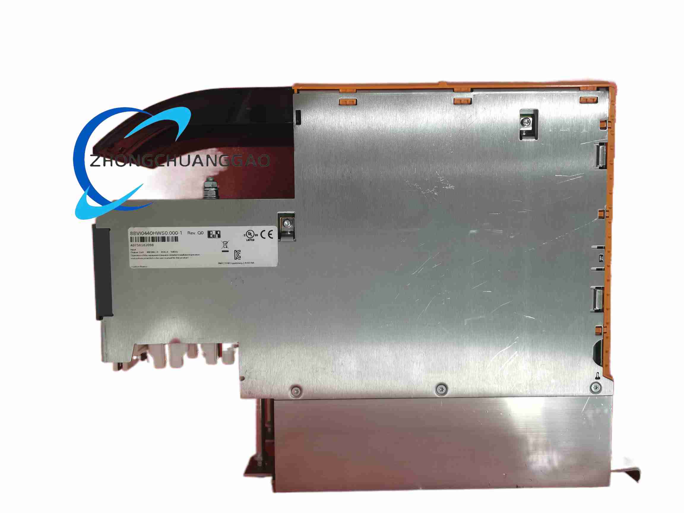
B&R 8BVI0440HWS0-000-1

Product Name​
ACOPOSmulti single-axis inverter module, wall-mount cooling version.
Product Introduction​
This inverter operates from the ACOPOSmulti common DC bus and drives synchronous servo or induction motors through PWM output stages. It is designed for modular multi-axis automation systems requiring centralized DC supply, regenerative energy sharing and plug-in safety/network options.
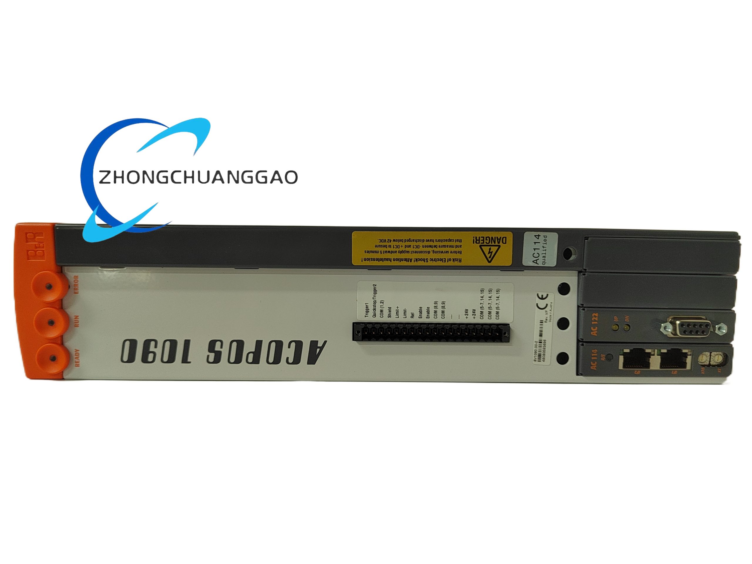
Detailed content

Technical Specifications​
  • DC bus voltage: 750 VDC nominal, 260–800 VDC operating range
  • Continuous output current: 44 Aeff
  • Peak output current: 88 Aeff for approximately 5 s
  • Continuous motor power: approximately 32 kW
  • Output voltage class: three-phase, derived from DC bus; approximately 0–480 VAC equivalent at full bus
  • Switching frequency: 5 kHz nominal, 10 kHz and 20 kHz selectable with derating
  • Auxiliary supply: 25 VDC via backplane, approximately ±1.6%
  • Option slots: 2 plug-in slots for network, encoder or SafeMOTION modules
  • Brake output: 24 VDC, 4.2 A continuous, short-circuit and open-circuit monitoring
  • Temperature sensor input: KTY84, PT1000 or PTC, approximately 500 Ω to 5 kΩ
  • Dimensions: 317 mm high, 106.5 mm wide, 263 mm deep
  • Weight: approximately 5.4 kg
Functional Features​
  • Shared DC-bus energy exchange between axes
  • Integrated safe-stop and safety option support
  • Holding-brake control and motor temperature monitoring
  • POWERLINK, encoder, resolver or safety expansion through option slots
  • Regenerative operation when paired with suitable supply module
Application Scenarios​
  • Multi-axis CNC, packaging, printing and robotics systems
  • Servo retrofit projects using common 750 VDC bus architecture
  • High-dynamic synchronous motor control
  • Production lines requiring centralized safety and motion networking
Performance Parameters​
  • Ambient temperature: 5–40°C nominal full rating, up to 55°C with derating
  • Storage temperature: -25°C to +55°C
  • Altitude: full ratings below 500 m, reduced current at higher altitude
  • Maximum output electrical frequency limited by safety monitoring, approximately 598 Hz trip threshold
  • Certifications: CE, UKCA, cULus E225616, KC and functional safety support per configuration
Material Composition​
  • Aluminum/steel wall-mount heatsink enclosure
  • Power semiconductor modules, DC-link capacitors and control PCB
  • EMC shielding plates, connector housings and option-card guides
Structural Characteristics​
  • Two-module-width wall-mount inverter with backplane DC-bus connection
  • Front option slots, motor power terminals, brake terminal and sensor input
  • Forced-air/convection cooling through integrated heatsink execution
Working Principle​
DC bus energy is switched by insulated power devices at the selected PWM frequency to produce three-phase motor voltage and current. The control section manages current regulation, encoder/resolver feedback, brake control and safety communication with the automation system.
Installation Requirements​
  • Mount on suitable wall plate with B&R backplane and required clearance for airflow
  • Connect DC bus only after verifying discharge and insulation tests
  • Install option cards, motor cables and shielded encoder cables per B&R wiring rules
  • Configure node address, motor parameters, switching frequency and safety functions in Automation Studio or drive engineering tools
Usage Precautions​
  • Wait for DC-link discharge and verify voltage below safe limit before service
  • Higher PWM frequency reduces continuous current; apply thermal derating
  • Do not exceed brake voltage, current and cable length recommendations
  • Use approved B&R motor and cable combinations to maintain EMC and insulation limits

You may also like