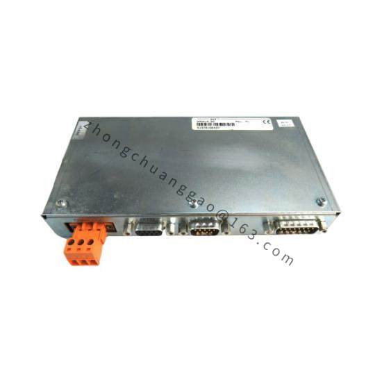
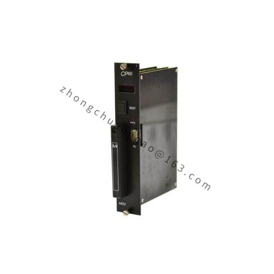
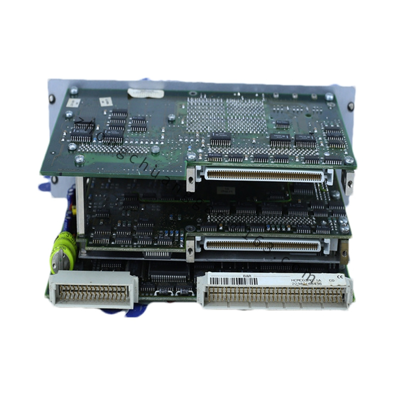
Technical Specifications: User SRAM 750 KB. User FlashPROM 1.5 MB. System FlashPROM 512 KB. Additional I/O processor for fast I/O handling. Average instruction cycle 0.5 µs. Fastest task class cycle 1 ms. Supply voltage 24 VDC nominal, operating range 18 VDC to 30 VDC. Maximum power consumption 20 W. I/O port output 12.15 W. RS232 interface 9-pin D-sub, maximum 57.6 kbit/s. CAN interface 9-pin D-sub, electrically isolated, maximum 500 kbit/s, maximum bus distance 1000 m. Four local screw-in module slots. One PCMCIA slot for PC cards. Backup lithium battery 3 V, 950 mAh. Real-time clock with 1 s resolution. Hardware watchdog and supply voltage monitoring.
Function Features: Separate I/O processor reduces CPU interrupt load. PCMCIA card support for software updates, logging and recipe data. Two CAN node-number rotary switches. Status LEDs for CPU, RS232, CAN, I/O modules and PCMCIA. System bus on left side for expansion modules.
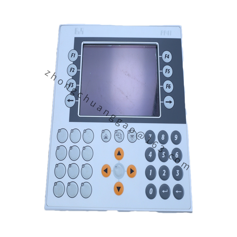
Application Scenarios: Machine automation with System 2003 I/O. Remote I/O expansion over CAN. HMI and printer connection through RS232. Legacy B&R control systems requiring PCMCIA storage.
Performance Parameters: Instruction cycle 0.5 µs average mixed bit/analog load. RS232 programming and visualization up to 57.6 kbit/s. CAN communication up to 500 kbit/s with electrical isolation. Local I/O through four screw-in slots plus left-side system expansion.
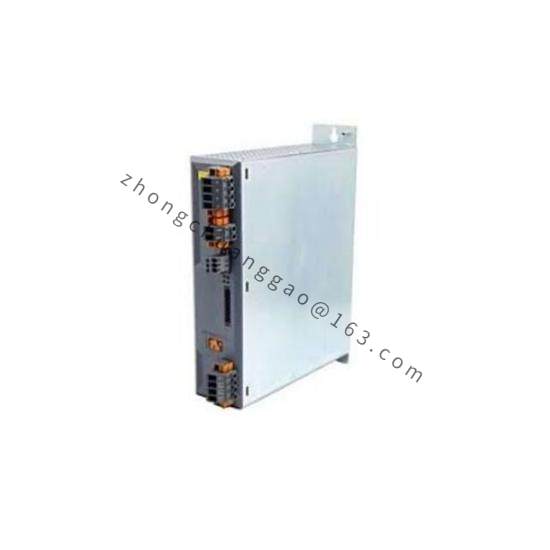
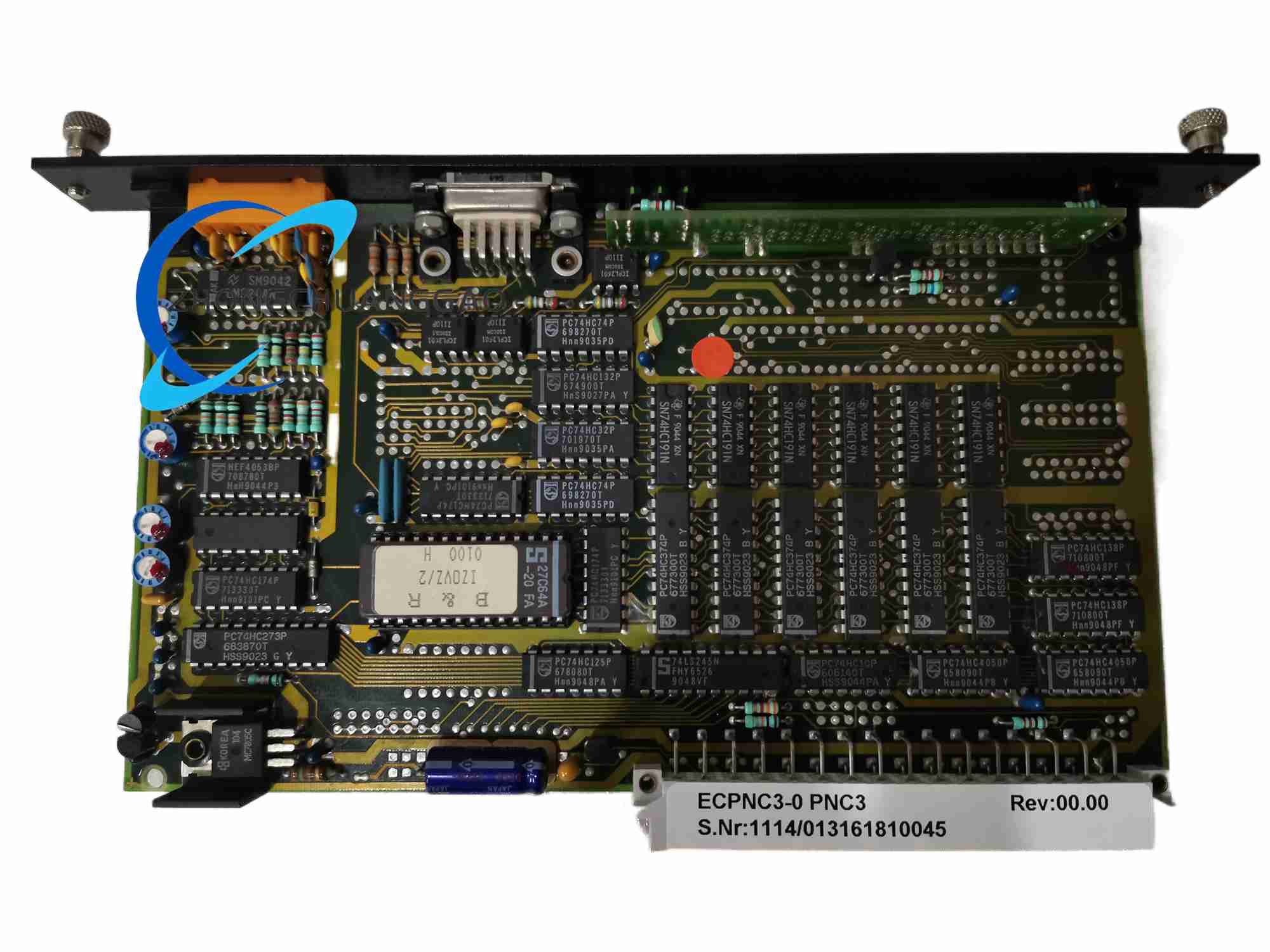
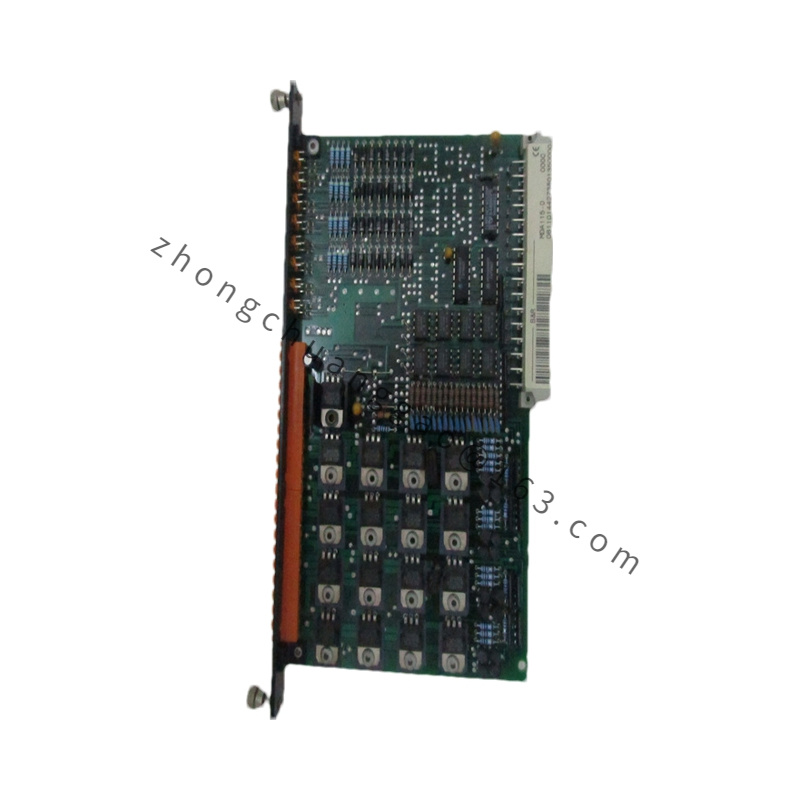
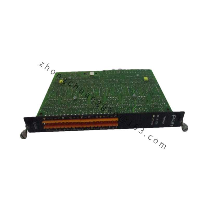
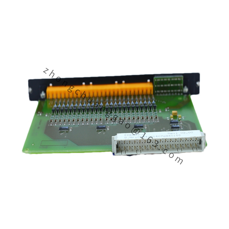
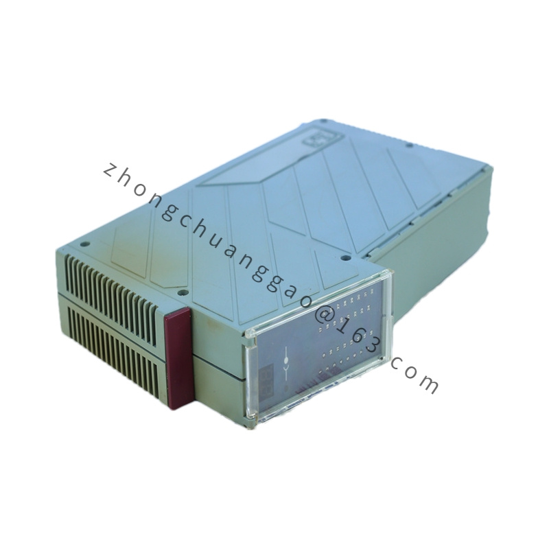
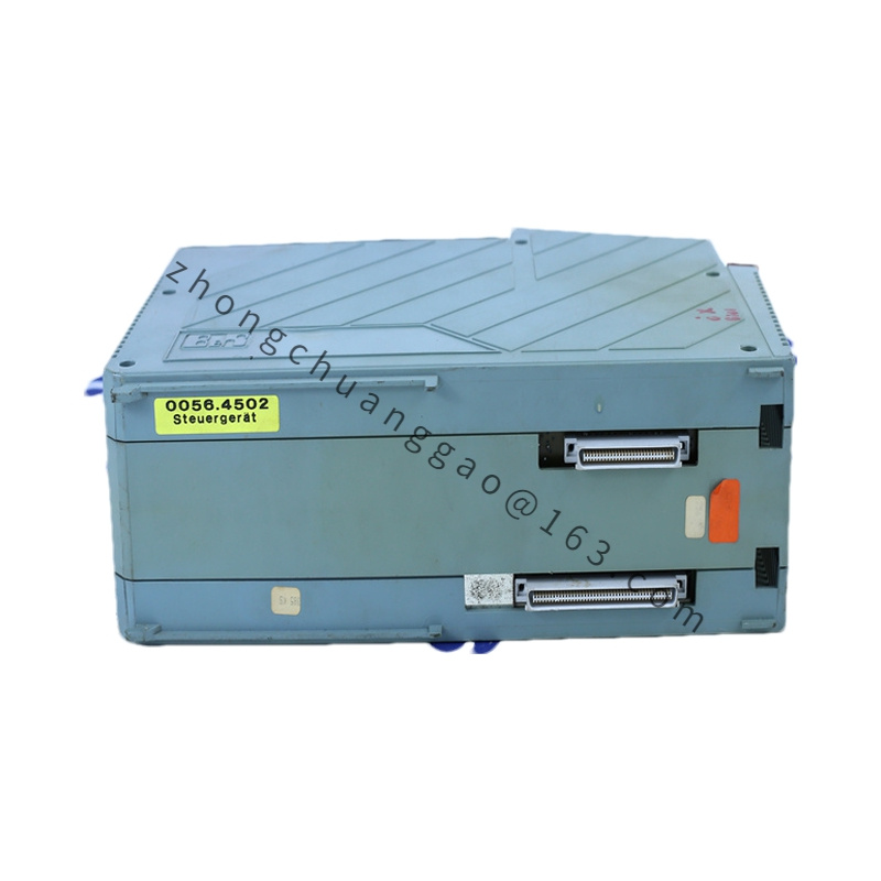
Material Composition: Double-width System 2003 module housing. Printed circuit board with microprocessor and I/O coprocessor. Lithium backup battery. D-sub connectors. Plastic front panel with LEDs and rotary switches.
Structure Characteristics: Right-side I/O bus for screw-in modules. Left-side system bus for PCMCIA and expansion adapters. Isolated CAN transceiver stage. Non-isolated RS232 stage.
Working Principle: The main CPU executes control programs and communication tasks. The I/O processor cyclically updates screw-in modules and reduces interrupt overhead. The CAN controller transfers I/O and network data with galvanic isolation. The PCMCIA interface provides nonvolatile storage and removable configuration media.
Installation Requirements: Mount in a System 2003 rack or CPU base. Connect 24 VDC supply with correct polarity and overcurrent protection. Insert PCMCIA card only with rated voltage and file format supported by the CPU. Set CAN node switches before network startup. Wire RS232 and CAN using shielded D-sub cables; terminate CAN according to network length and baud rate.
Usage Precautions: CAN is isolated; RS232 is not isolated, so use additional protection in noisy environments. Replace the lithium battery only with the specified 3 V 950 mAh type. Do not exceed 30 VDC input. Observe ESD precautions when handling modules and PCMCIA cards. Verify firmware and PCMCIA compatibility before downloading programs.