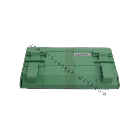
B&R 5P81451322
Product Name
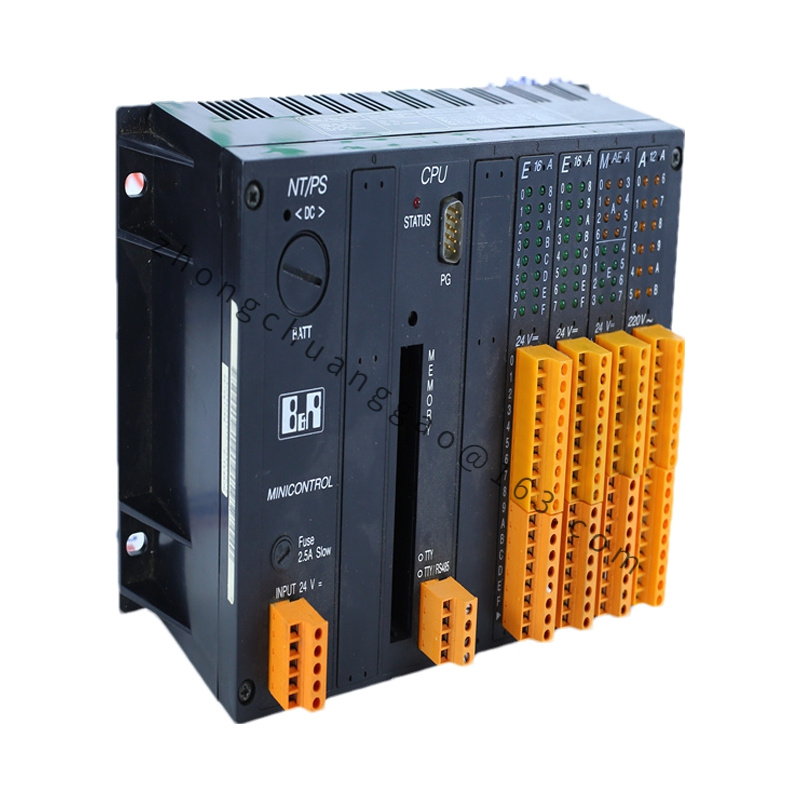
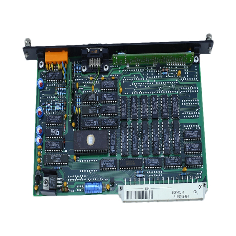
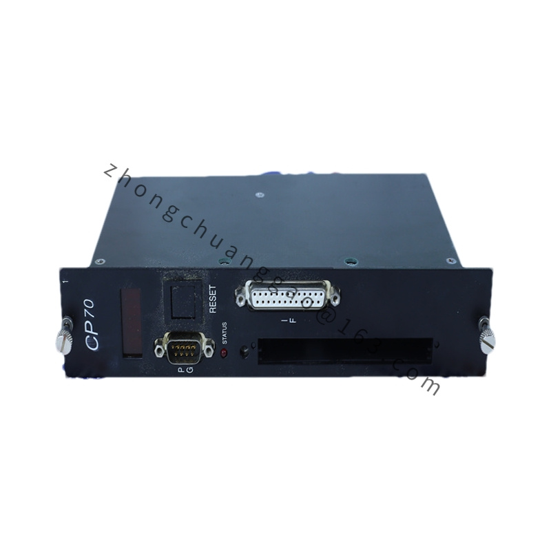
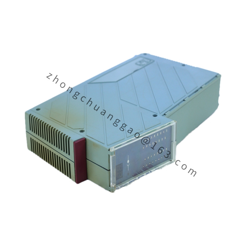
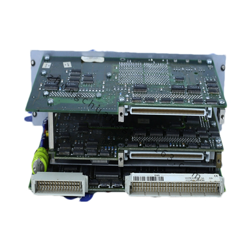
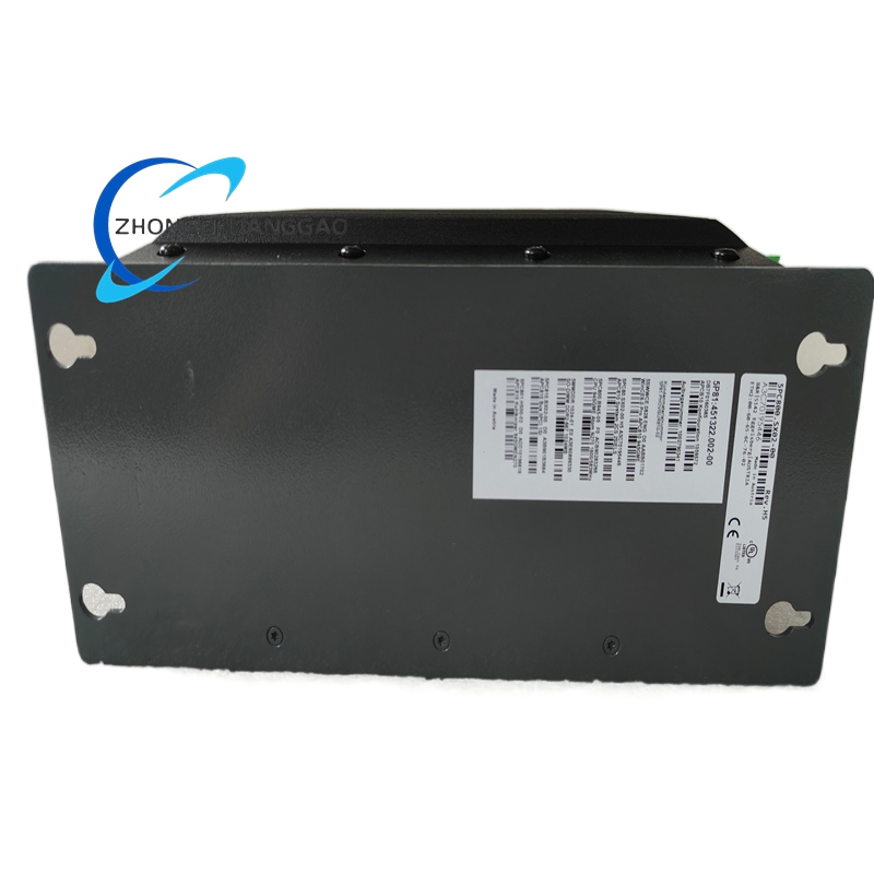
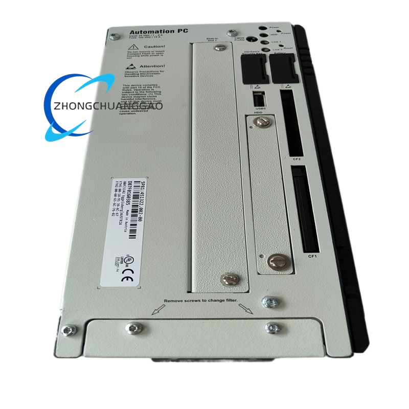
B&R 5P81451322 Multi-Slot Automation PC 810 Industrial Computer Assembly
Product Overview
The 5P81451322 number is supplied in industrial spare-parts sources as a configured B&R Automation PC 810 multi-slot industrial PC assembly. The 5P81451322.002-00 build provides a box-style IPC system unit with Intel x86 CPU options, industrial Ethernet, display output and PCI expansion for real-time control, visualization and fieldbus communication.
Detailed content
Technical Specifications
Product family: B&R Automation PC 810
Configured material example: 5P81451322.002-00
Operating voltage: 24 VDC nominal, ±25%, isolated input according to assembly build
Processor options: Intel Core 2 Duo, Core Duo or Celeron M according to installed CPU board
Memory: 2 x DDR2 SO-DIMM slots; capacity depends on installed modules
Retain memory: 512 kB battery-backed SRAM for nonvolatile parameters according to comparable APC810 system units
Ethernet: 2 x 10/100/1000 Mbit/s RJ45 ports
Display: DVI-I with direct DVI or VGA and optional Smart Display Link transmitter
Serial: 2 x RS232 9-pin DSUB according to configuration
USB: up to 5 x USB 2.0 according to installed interface build
Expansion: multi-slot PCI or mixed PCI/PCIe backplane according to ordered variant
Storage: internal slide-in drive bays and CompactFlash according to system configuration
Cooling: passive heatsink chassis cooling for listed industrial builds
Operating temperature: 0 to 55°C according to B&R APC810 environmental data
Functional Features
Real-time PLC, motion and HMI hosting under B&R Automation Runtime
Battery-backed SRAM for retentive variables and recipe data
Gigabit Ethernet for controller networking, SCADA and software deployment
PCI slots for fieldbus cards such as POWERLINK, PROFIBUS or additional serial interfaces
Smart Display Link support for long-distance B&R Automation Panel connection
Application Scenarios
CNC and high-speed packaging machines
Multi-axis motion control with centralized I/O
Manufacturing cells requiring real-time PLC and visualization in one chassis
Legacy B&R APC810 cabinet upgrades and spare-unit replacement
Performance Parameters
Ethernet throughput: 10/100/1000 Mbit/s per port
Serial throughput: RS232 up to 115 kbit/s per port according to CPU and UART build
SRAM retain capacity: 512 kB in comparable B&R system units
Backplane expansion: defined by the ordered PCI, PCI-X or PCIe mix
Material Composition
Chassis: heavy-duty galvanized steel according to spare-part documentation
Mainboard: industrial Intel x86 CPU board with DDR2 memory sockets
Storage carriers: slide-in drive bays and CompactFlash holders
Cooling parts: passive heatsinks and chassis conduction surfaces
Connectors: RJ45, DVI-I, DSUB and USB industrial-grade interfaces
Structural Characteristics
Box IPC form factor for control-cabinet mounting
Removable CPU board, storage modules and expansion cards
Front or top service access according to the assembled chassis version
Dedicated slots for fieldbus communication and visualization transmitters
Working Principle
The CPU board executes the B&R runtime and application code. Ethernet ports handle programming, HMI and plant network traffic. The DVI-I or SDL interface sends video to local monitors or remote Automation Panels. PCI/PCIe slots carry fieldbus and I/O cards. Battery-backed SRAM preserves critical variables during power loss, while slide-in storage holds the operating system and project image.
Installation Requirements
Confirm the complete material number, CPU board, RAM, storage and slot configuration before installation.
Provide 24 VDC ±25% SELV supply sized for the installed boards and drives.
Mount the chassis in a cabinet with cooling capacity for the configured processor load.
Install B&R Automation Studio and matching firmware before restoring the project.
Use B&R-approved CompactFlash, SDL cables and fieldbus cards.
Usage Notes
Do not interchange 5P81451322 suffix builds without checking CPU, memory and slot layout.
Replace the SRAM battery according to the service interval stated on the specific battery pack.
Verify PCI card voltage and bus type before inserting communication modules.
Keep cabinet temperature within the configured operating range of the installed CPU board.