Program Memory
850 KB SRAM, 1.5 MB FlashPROM.
Digital Inputs
Up to 12 channels, 24 VDC, sink type.
Digital Outputs
Up to 12 channels, 24 VDC, 0.1 A per channel.
Analog Inputs
6 channels, ±10 V, 14-bit resolution.
Analog Outputs
6 channels, ±10 V, 12-bit resolution.
RS232 Interface
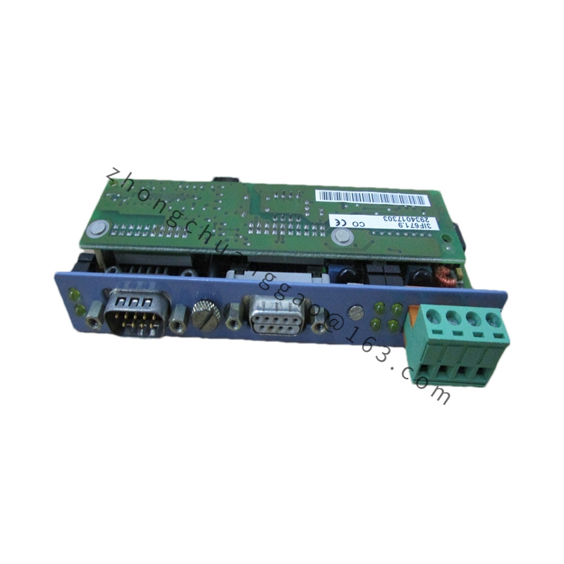
One serial port for programming, visualization or external devices.
CAN Interface
One electrically isolated CAN port for network integration.
CPU Capability
Operates as interface processor or as CPU in supported slot configuration.
Terminal Requirement
Use 3× TB170 terminal blocks for field wiring.
Housing Material
System 2005 industrial module body, FR4 PCB, screw-terminal contacts.
Mechanical Structure
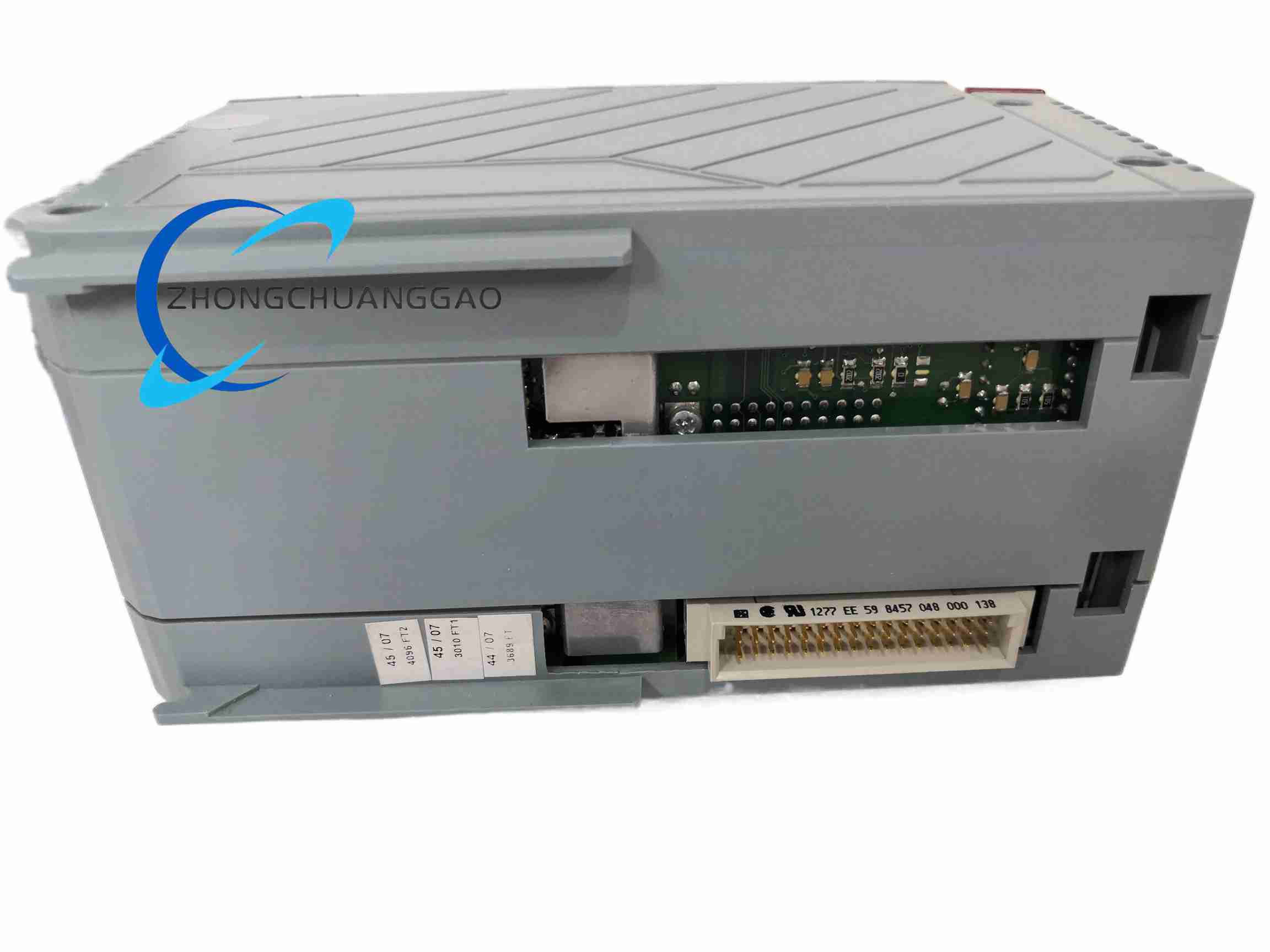
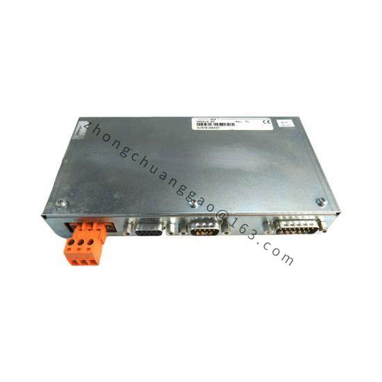
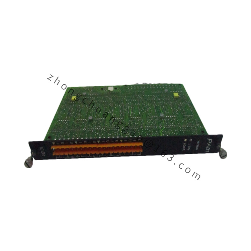
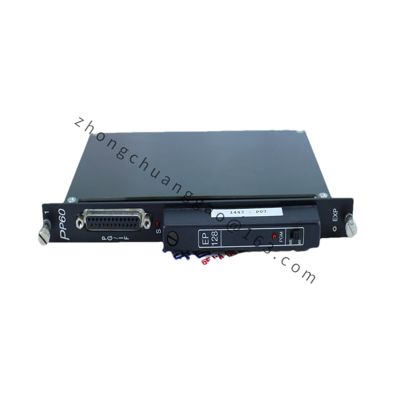
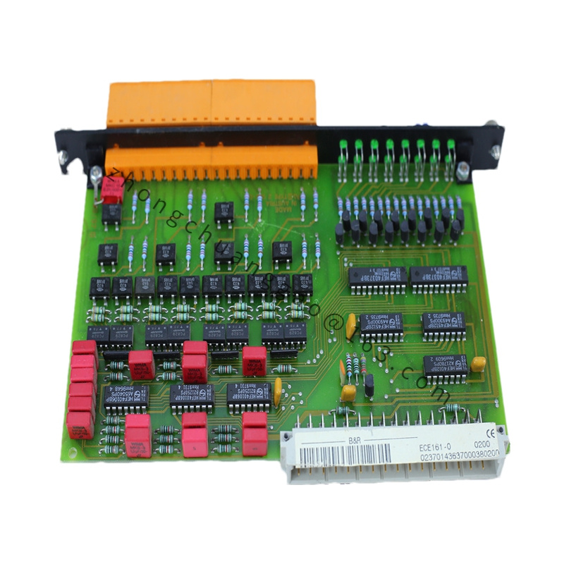
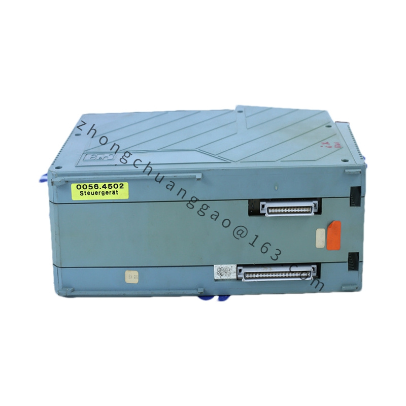
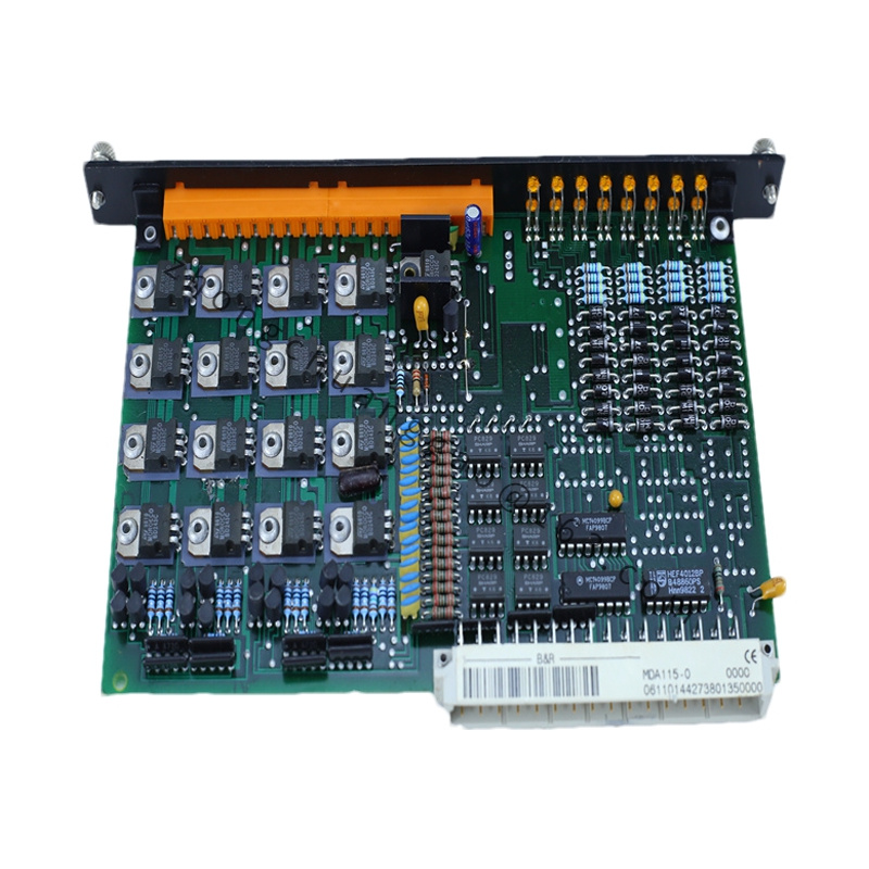
2005 backplane module, front communication and status elements, grouped digital and analog terminals, DIN/backplane mounting format.
Working Principle
The onboard processor executes the I/O program, scans digital inputs and outputs, converts analog signals through ADC and DAC stages, and handles RS232 or CAN message exchange. In interface mode, it preprocesses data and transfers it to the central CPU. In CPU mode, it controls local and expanded I/O directly.
Special I/O Functions
Interrupt-capable digital channels, high-speed analog capture with FIFO mode, and comparator mode for threshold-based event processing.
Installation Requirements
Mount the module in the designated 2005 baseplate. Install TB170 terminal blocks according to the digital and analog wiring plan. Set station and slot configuration per the 2005 system design. Use shielded CAN and analog cables with proper earth grounding.
Usage Precautions
Do not exceed 0.1 A per digital output. Connect only 24 VDC sink-type input devices unless the system configuration defines otherwise. Calibrate analog ranges before startup. Inspect terminal blocks monthly. Avoid electrostatic discharge when handling the module.