Technical Specifications
Standard small-field versions: 2 A continuous field output, 4 A peak according to DECS-200-2x family documentation; verify ordered field class before application.
Expanded project versions: public third-party listings describe 200 A continuous and 400 A peak configurations, but these ratings must be confirmed against the exact Basler order code.
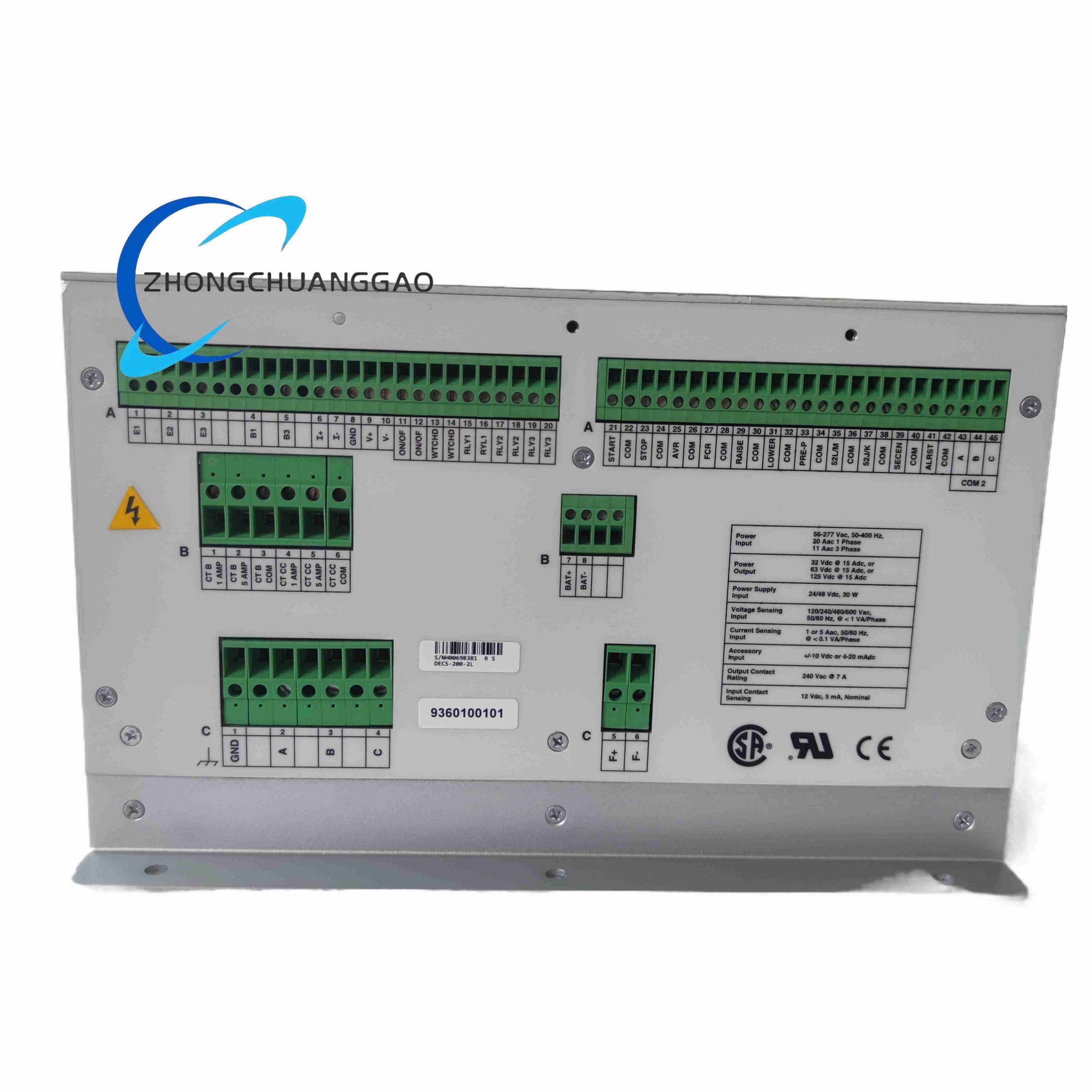
Sensing: single-phase or three-phase true RMS voltage and current according to configuration.
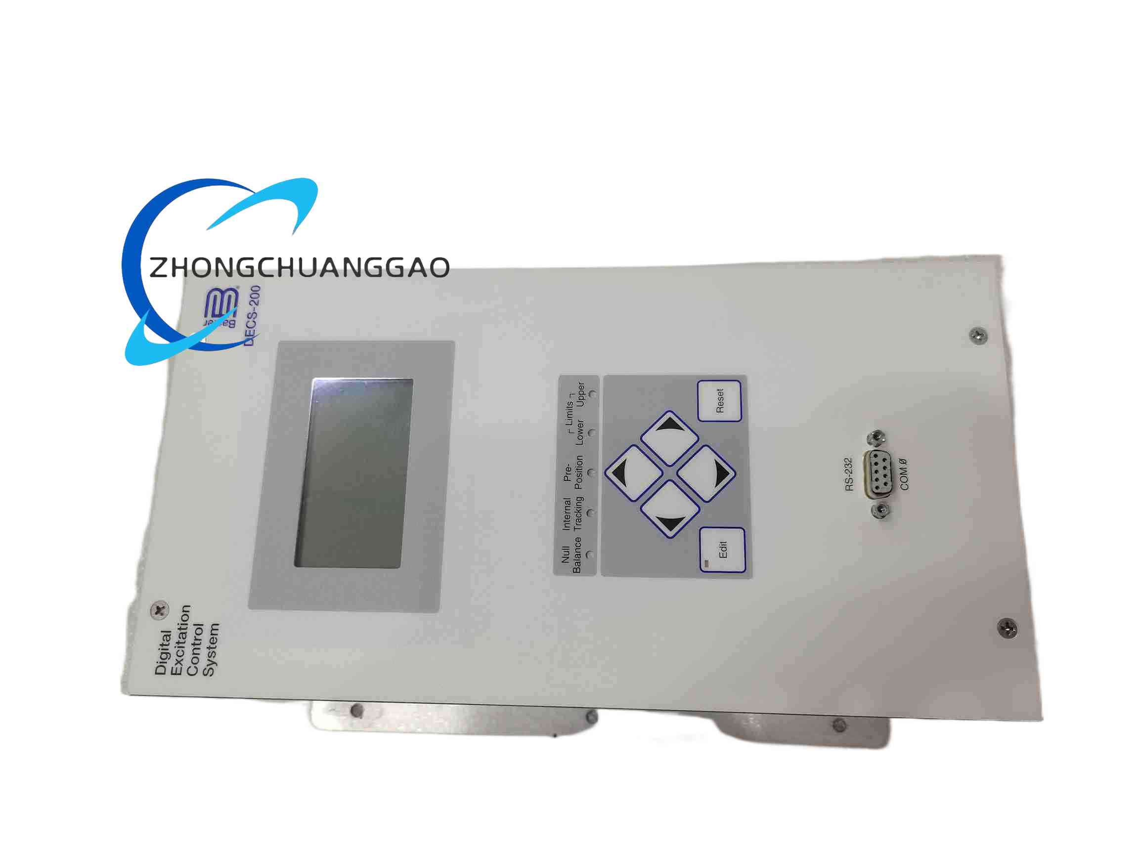
Communication: RS232 and RS485 Modbus; extended versions add Ethernet or additional network ports according to order code.
Operating temperature: -40°C to +70°C according to enhanced 2L listings; verify against the delivered unit label.
Functional Features
Automatic voltage regulation, manual field current regulation and limiter functions.
Parallel operation support, load sharing, var droop and reactive compensation according to enabled configuration.
Generator protection including over/undervoltage, over/underfrequency, field limits and loss-of-field functions.
Event recording, metering and remote communication according to configuration.
Performance Parameters
Regulation accuracy: ±0.25% for standard DECS-200 AVR configurations.
Forcing response and transient performance depend on field voltage class, generator field resistance and ordered power stage.
Communication distance depends on RS485 cable, baud rate and termination.
Material Composition
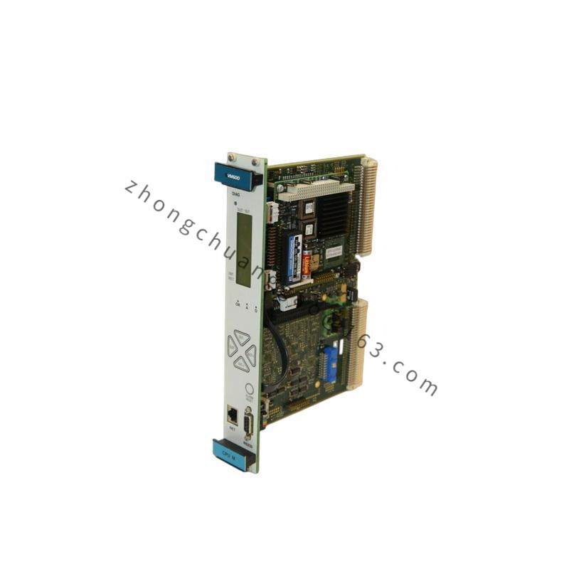
Control enclosure with DSP or microprocessor control board.
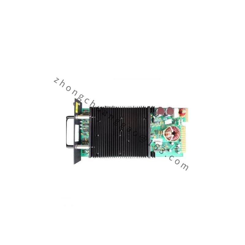
Field power stage using thyristors, MOSFETs or IGBTs according to output class.
Sensing, isolation, protection and communication circuit boards.
Industrial terminals, fans or heatsinks according to power rating.
Structural Features
Panel or rack mounting according to output class.
Front display or service port for configuration.
Separated PT, CT, field, control input and communication terminals.
Working Principle
The controller measures generator electrical quantities, compares them with setpoints and generates excitation commands. The power stage converts control commands into field current. Limiters, protection functions and parallel-compensation algorithms adjust excitation to maintain voltage stability, reactive sharing and safe generator operation.
Installation Requirements
Confirm exact field current class from the nameplate before installation.
Match PT/CT ratios, field winding resistance and exciter type.
Use shielded twisted pair for sensing and communication cables.
Provide termination resistors only at RS485 physical ends when Modbus is used.
Install in a cabinet with cooling capacity suitable for the ordered power stage.
Usage Precautions
Do not assume 2 A, 15 A or 200 A rating without checking the unit nameplate.
Validate all limiter settings before parallel operation.
Test protection trips and forcing functions under controlled no-load and load conditions.
Keep firmware and configuration backup.
Disconnect field and control supplies before servicing.