Technical Specifications
System compatibility: Bachmann M1 automation platform
Digital inputs: 32 channels, 24 VDC
Digital outputs: 32 channels, 24 VDC
Output current: 0.5 A maximum per channel
Input current: 2 to 3 mA per channel
Galvanic isolation: 1500 V RMS between channels, bus and ground
Interrupt inputs: 8 hardware interrupt channels
Counter channels: 4 high-speed 32-bit counters
PWM output: configurable, valve economy hold time 0 to 2 s
Response time: input below 5 ms, output below 2 ms
Supply voltage: 18 to 34 VDC, reverse-polarity protected
Power consumption: 8 to 10 W
Operating temperature: -30 to +60 C
Storage temperature: -40 to +85 C
Humidity: 5 to 95 percent non-condensing
Dimensions: 130 x 50 x 150 mm
Weight: 0.55 kg
Certification: CE, UL, RoHS
Functional Features
Per-channel LED diagnostics
Short-circuit and overload indication on outputs
Hardware interrupt reporting bypasses standard scan delay
High-speed counting for encoders, flow meters and frequency measurement
PWM control reduces holding power for solenoid valves
Firmware configuration through M1 bus tools
Application Scenarios
Discrete manufacturing lines
Conveyor and packaging systems
Renewable energy and turbine control panels
Rail and infrastructure automation cabinets
High-channel-count machine I/O clusters
Performance Parameters
Input logic threshold matches 24 VDC sensor levels
Output switching supports resistive, inductive and lamp loads within 0.5 A
Interrupt latency supports sub-millisecond event capture
Counter inputs operate with proximity switches, encoders and pulse meters
PWM resolution supports energy-saving valve control
Material Composition
Module housing uses high-strength industrial polyamide
Internal multilayer printed circuit boards with isolated power domains
Spring or screw terminal contacts use tinned copper alloy
Semiconductor outputs use solid-state switching elements with freewheeling protection
Structural Characteristics
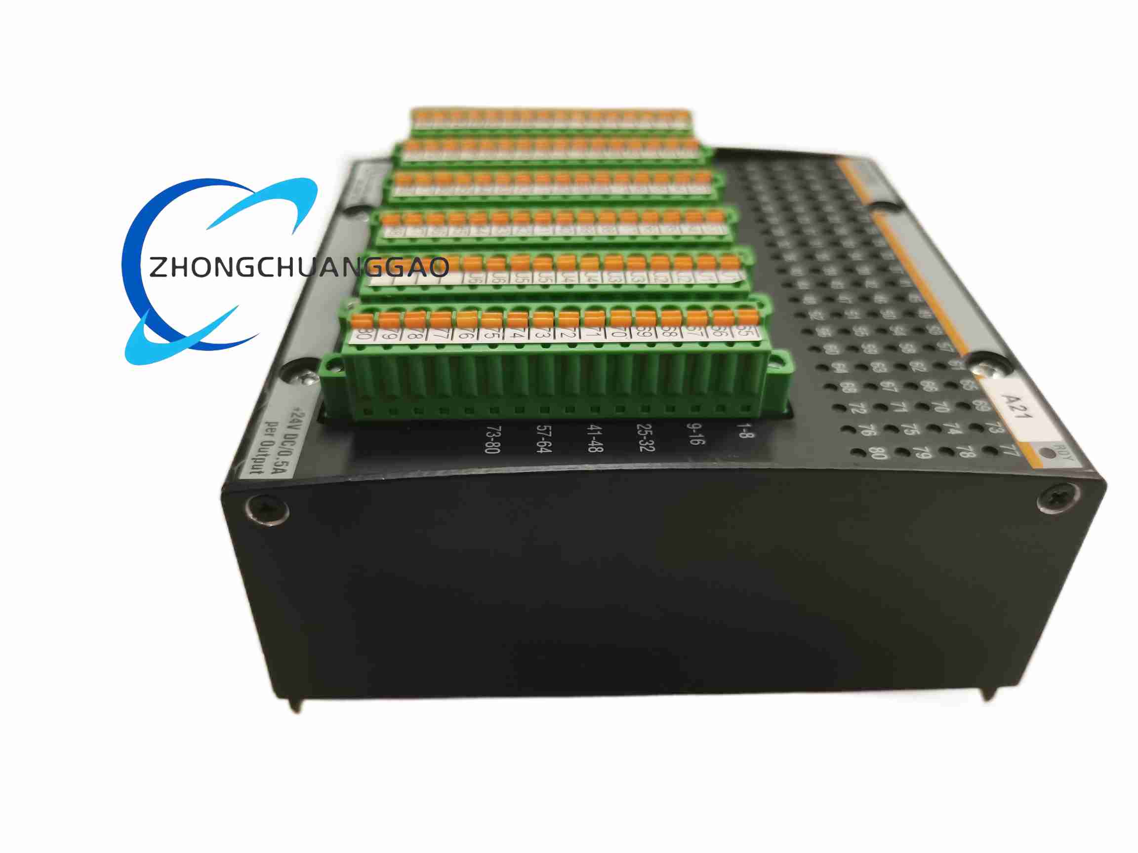
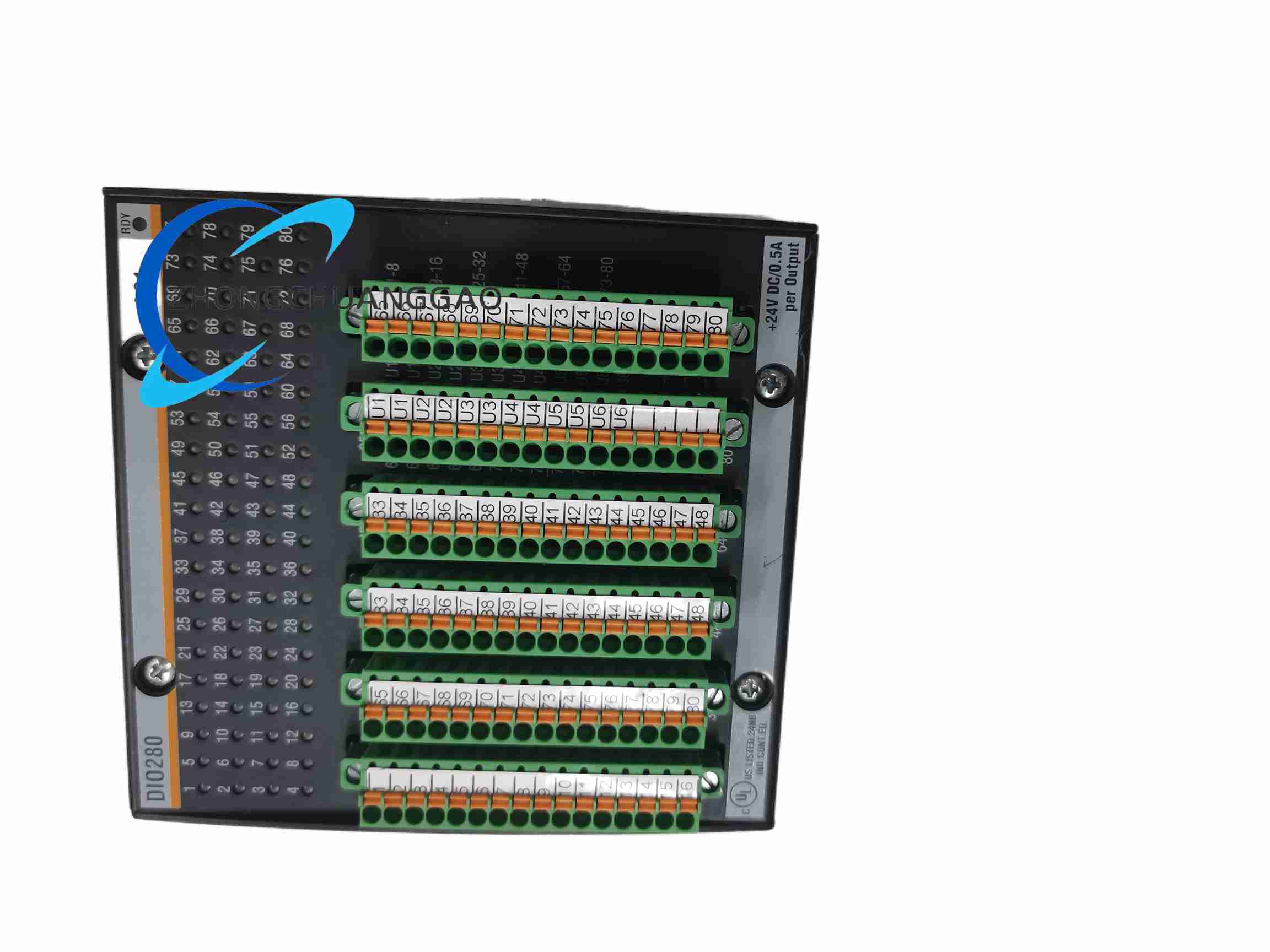
Single-slot M1 backplane form factor
Pluggable spring or screw terminal blocks
Integrated bus connector for M1 rack communication
Front LED array for channel and bus status
DIN-rail or M1 rack mounting version
Working Principle
Field sensors apply 24 VDC discrete signals to input channels. Input circuits filter, isolate and transmit status to the M1 controller over the backplane bus. Control programs return output commands through the bus to solid-state drivers. Output channels switch 24 VDC actuators, solenoids or indicators. Interrupt inputs send edge events directly to the CPU. Counter channels process pulse trains independently of the main scan. PWM channels modulate output voltage and current for reduced thermal loss.
Installation Requirements
Mount on 35 mm DIN rail or designated M1 rack station
Provide 18 to 34 VDC controlled supply with reverse-polarity protection
Keep 20 mm free airflow space above and below the module
Separate 24 VDC signal cables from AC power and VFD cables
Connect cable shields to the cabinet ground bar before module termination
Verify M1 backplane address and firmware before power-up
Usage Precautions
Do not exceed 0.5 A per output channel
Do not exceed 24 VDC nominal field voltage
Avoid mixing separate 0 V power supplies on common input groups
Perform firmware and configuration backup before replacement
Maintain ambient temperature within -30 to +60 C