Technical Specifications
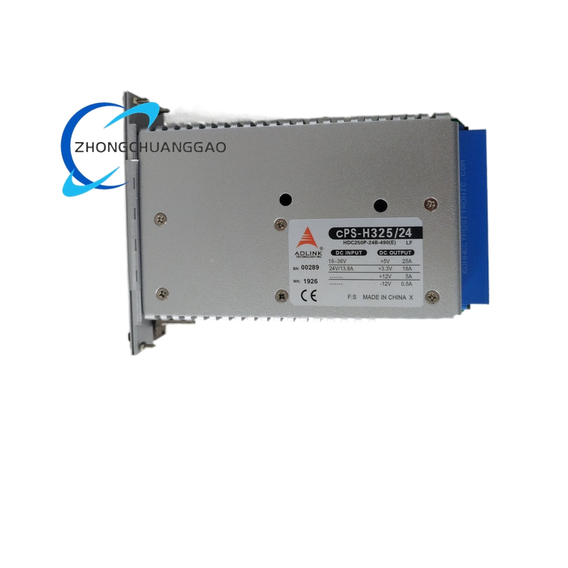
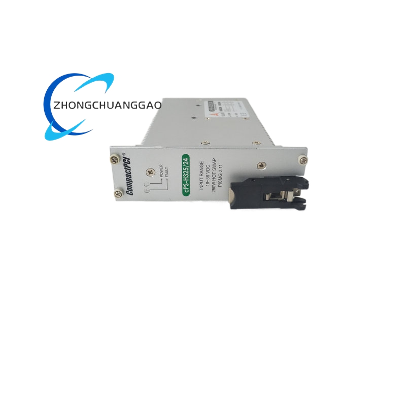
Input voltage 18 VDC to 36 VDC, typical 24 VDC nominal. Output rails +3.3 V, +5 V, +12 V and -12 V through PICMG 2.11 47-pin CompactPCI power connector. Total output power 250 W. Published current allocations include +3.3 V up to 33 A, +5 V up to 33 A, +12 V up to 5 A and -12 V up to 0.5 A for selected configurations; other redundant builds allocate +3.3 V, +5 V and +12 V differently according to the chassis load plan. Efficiency approximately 79% to 85% depending on load and configuration. Interface PICMG 2.11, optional I2C diagnostics. Hot-swap OR-ing diodes for parallel redundancy. Protection overcurrent, overvoltage, overtemperature and short-circuit. Dimensions 3U CompactPCI 8HP width, approximately 160 mm board height with chassis depth according to backplane. Operating temperature 0°C to +70°C for standard builds and -40°C to +70°C for selected extended-temperature builds.
Functional Features
N+1 redundant operation with automatic load sharing. Hot-swap insertion and extraction under PICMG 2.11 power sequencing. I2C status reporting for output voltage, current, temperature and fan/fault conditions. Internal OR-ing diodes eliminate external isolation diodes in parallel shelves. Regulated output with low ripple for logic, peripheral and disk loads.
Materials And Structure
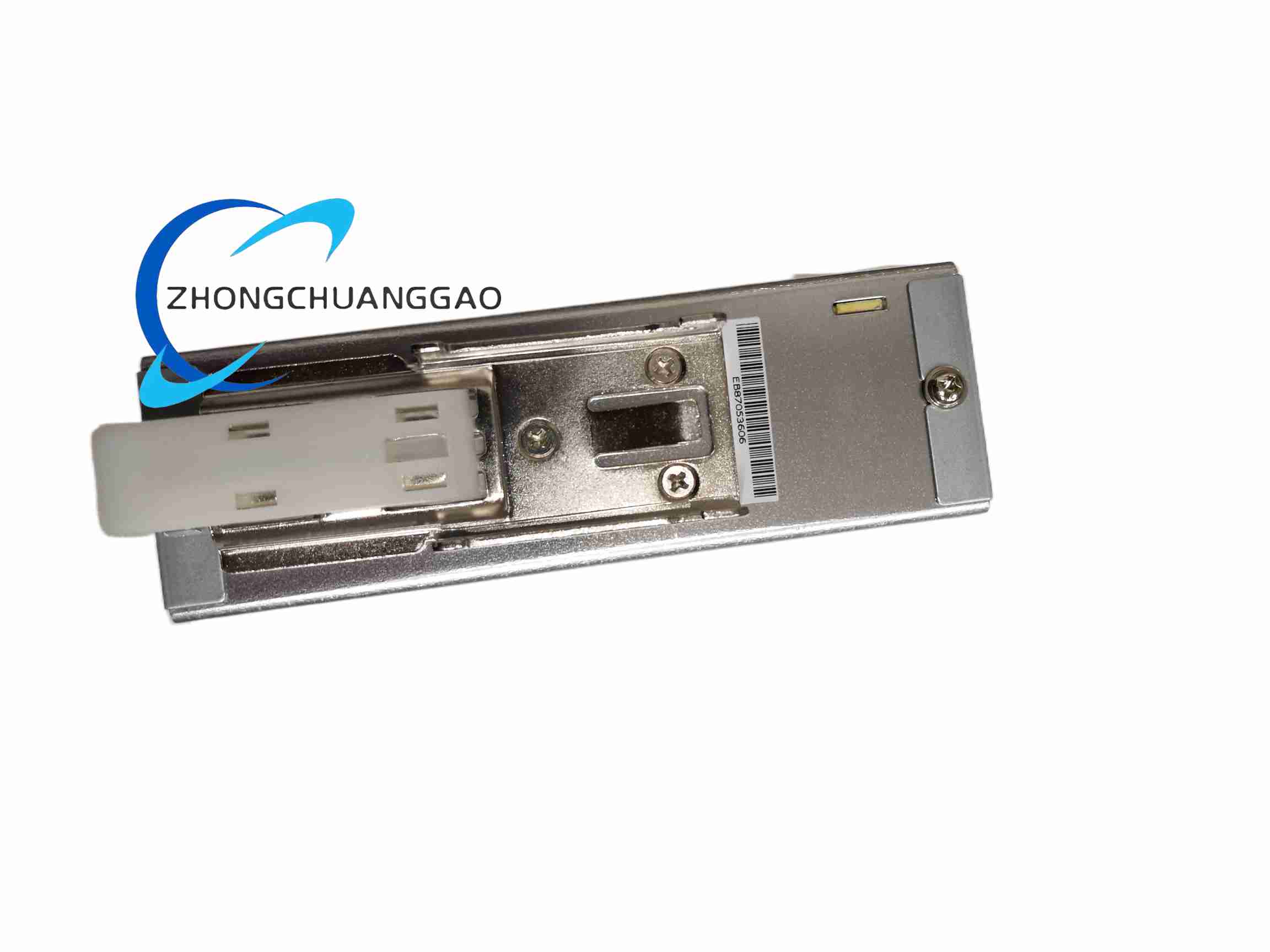
Switch-mode power PCB with high-Tg FR-4, DC/DC converters, EMI filtering and output filtering. 3U aluminum heatsink or chassis-conduction frame. 47-pin PICMG 2.11 power connector. Hot-swap handle with inrush-limiting circuit. Variable-speed or controlled fan cooling depending on configuration.
Working Principle
DC input passes through fuse/EMI filtering and wide-range DC/DC stages. Each stage regulates one output rail with feedback compensation and current limit. The 3.3 V and 5 V rails supply logic and memory; +12 V supplies disks, displays and serial interfaces; -12 V supplies analog or legacy interfaces. OR-ing diodes combine modules in parallel so a failed unit can be removed without interrupting the backplane. I2C reports telemetry to the chassis manager.
Installation Requirements
Install in a dedicated 8HP CompactPCI power slot with PICMG 2.11 47-pin backplane. Confirm input source is within 18 VDC to 36 VDC and sized for total shelf load plus redundancy headroom. Connect chassis ground, earth and backplane power plane before energizing. For N+1 systems, populate the planned number of modules and verify load share balance. Provide airflow or conduction cooling path according to the 250 W thermal rating.
Usage Precautions
De-energize or follow hot-swap procedure before replacing the module. Do not exceed 36 VDC input or the rated current of each output rail. Verify output polarity and backplane pinout before first power-on. Monitor I2C fault flags for undervoltage, overtemperature or fan stall. Use only matching cPS-H325/24 revisions in parallel redundant shelves to avoid load-share imbalance.