Technical Specifications
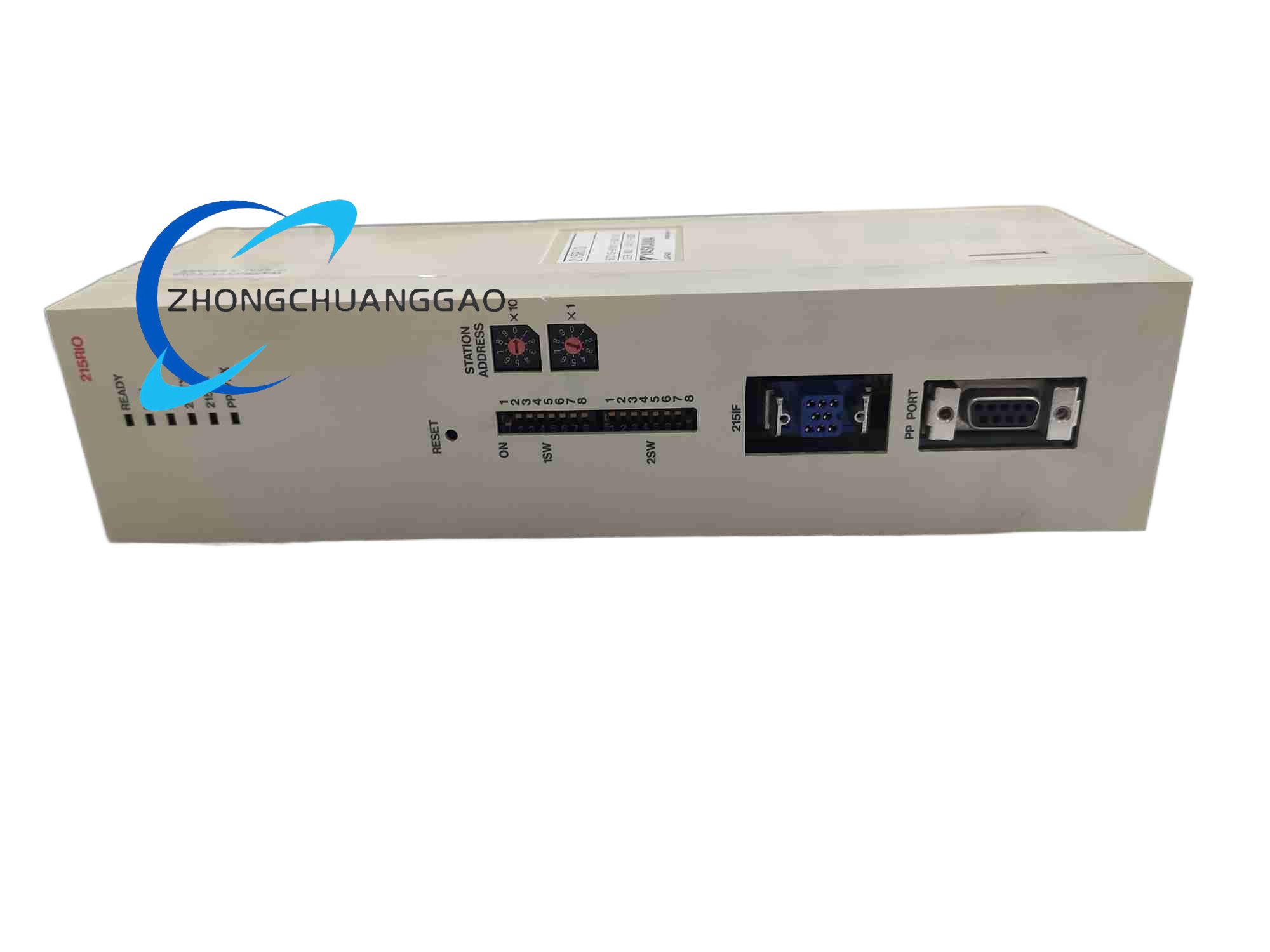
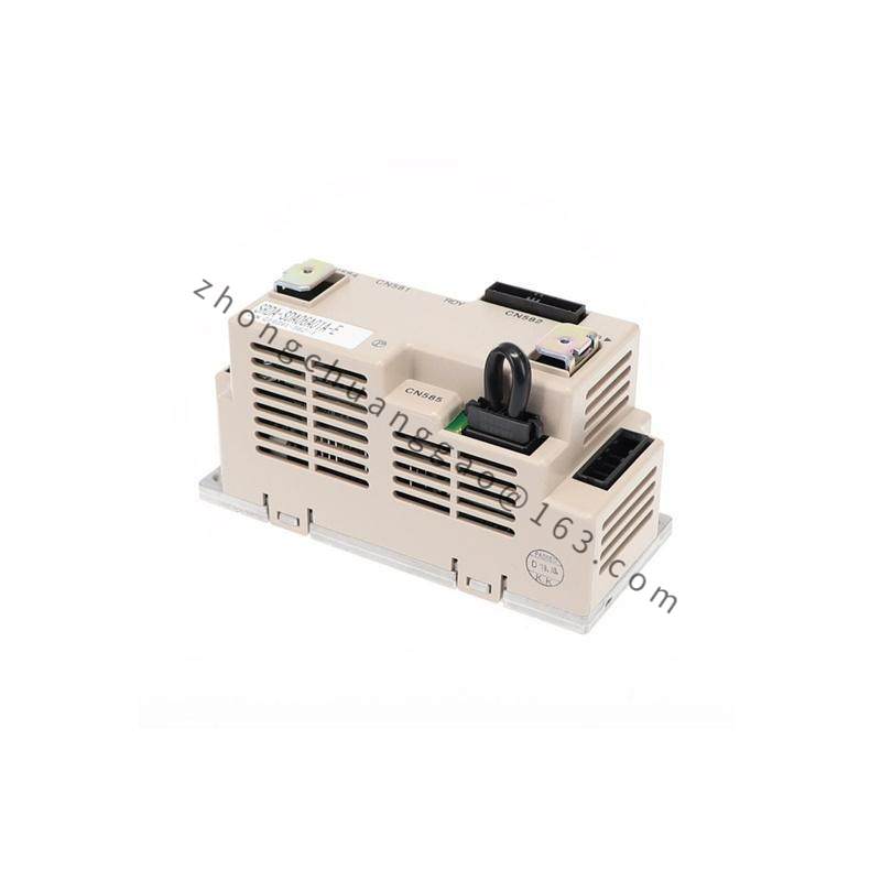
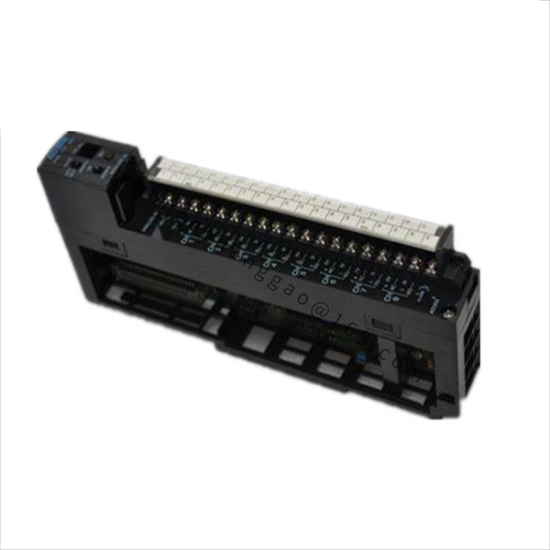
Module type: remote digital I/O module
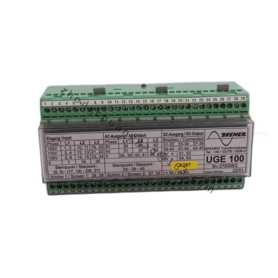
Power supply: 24 VDC nominal
Communication: dedicated Yaskawa motion bus with RS-422 and RS-485 support
Operating temperature: 0 to +45 °C
Humidity: 90 percent maximum, non-condensing
Mounting: standard DIN rail
Indicators: channel-level LED status lamps
Protection: output short-circuit protection
Functional Features
Expands discrete input and output points for robot or motion controllers
Exchanges remote I/O data with the main controller in real time
Protects output channels against short-circuit conditions
Provides per-channel status indication for rapid diagnostics
Captures high-speed sensor signals for automation sequences
Application Scenarios
Industrial robot peripheral sensor and actuator signal expansion
Automated assembly cells and machine-tending workstations
Material-handling robotic systems
Distributed I/O collection for Yaskawa motion control racks
Performance Parameters
Bus update cycle matches the robot or motion controller communication timing
Channel-level fault indication supports maintenance diagnosis
Input filtering and output driving are optimized for 24 VDC industrial signals
Short-circuit protection limits damage during wiring faults
Material Composition
Housing: flame-retardant ABS plastic
Internal circuit: industrial-grade multilayer PCB
Terminals: spring-clamp or screw-type terminal block according to configuration
Connectors: bus input and bus output industrial interfaces
Structural Characteristics
DIN-rail mounting form factor for control cabinet installation
Front-face LED indicators for each I/O channel
Separate bus-in and bus-out connectors for daisy-chain topology
Dedicated 24 VDC power terminal group
Clearly separated input and output wiring areas
Working Principle
Field digital sensors send on/off signals to the input circuits. The module transmits input status over the dedicated motion bus to the main controller. The controller returns output commands through the same bus, and the output stage switches actuators such as relays, solenoids, indicators and robot peripheral devices.
Installation Requirements
Mount on a standard DIN rail inside a ventilated control cabinet
Use 24 VDC power supply with correct polarity and adequate current rating
Connect bus-in and bus-out cables with shielded industrial cable
Keep clearance around the module for natural convection cooling
Set node or address parameters according to the controller I/O configuration
Usage Notes
Do not exceed the rated current of each output channel
Keep humidity non-condensing to avoid internal circuit damage
Separate signal cables from high-power motor drive cables
Verify bus node address before applying power
Inspect terminal tightness and LED status during commissioning