-
Technical Specifications:
-
Analog Version:
-
Position Command: 0–5 Vdc or 4–20 mA analog; or PWM
-
Output Shaft: 0.625-36 serrated tooth; 72.5° rotary output (±2°) for direct butterfly valve coupling
-
Mounting: Base or flange mount (Model IV base-mount only)
-
Environmental: Withstands extreme vibration and high temperature
-
Digital Plus Version:
-
Position Command: Analog, PWM, or CAN (single or redundant)
-
Driver: Integrated digital driver with CAN communication
-
Diagnostics: Online/offline diagnostics, current limiting based on driver electronics temperature, event logging
-
Configuration: Field-programmable via RS-232 using Woodward ProAct Service Tool and Watch Window Service software
-
Fault Annunciation: Monitors all internal/external signals; discrete output for detected faults
-
Standby: Discrete input for remote low-power standby mode
-
Analog Output: 0–25 mA actual position indication
-
Functional Features:
-
All-electric, no external hydraulic or pneumatic supply required
-
Extremely fast bidirectional actuation, electronically positioned in both directions
-
Eleven-point curve function for non-linear output behavior
-
Redundant position command with automatic failover
-
CAN-based communications for control and service
-
Advanced on-board diagnostics and event log
-
Working Principle: Receives a position command from an external speed control or engine management system, compares it to internal position feedback, and drives the electric motor to achieve the commanded rotary position. The Digital Plus driver manages motor commutation, current limiting, and fault detection while communicating status over CAN.
-
Application Scenarios: Fuel rack positioning on diesel and gas engines; engine timing control; throttle valve control; wastegate positioning; direct coupling to butterfly valves (eliminating linkage).
-
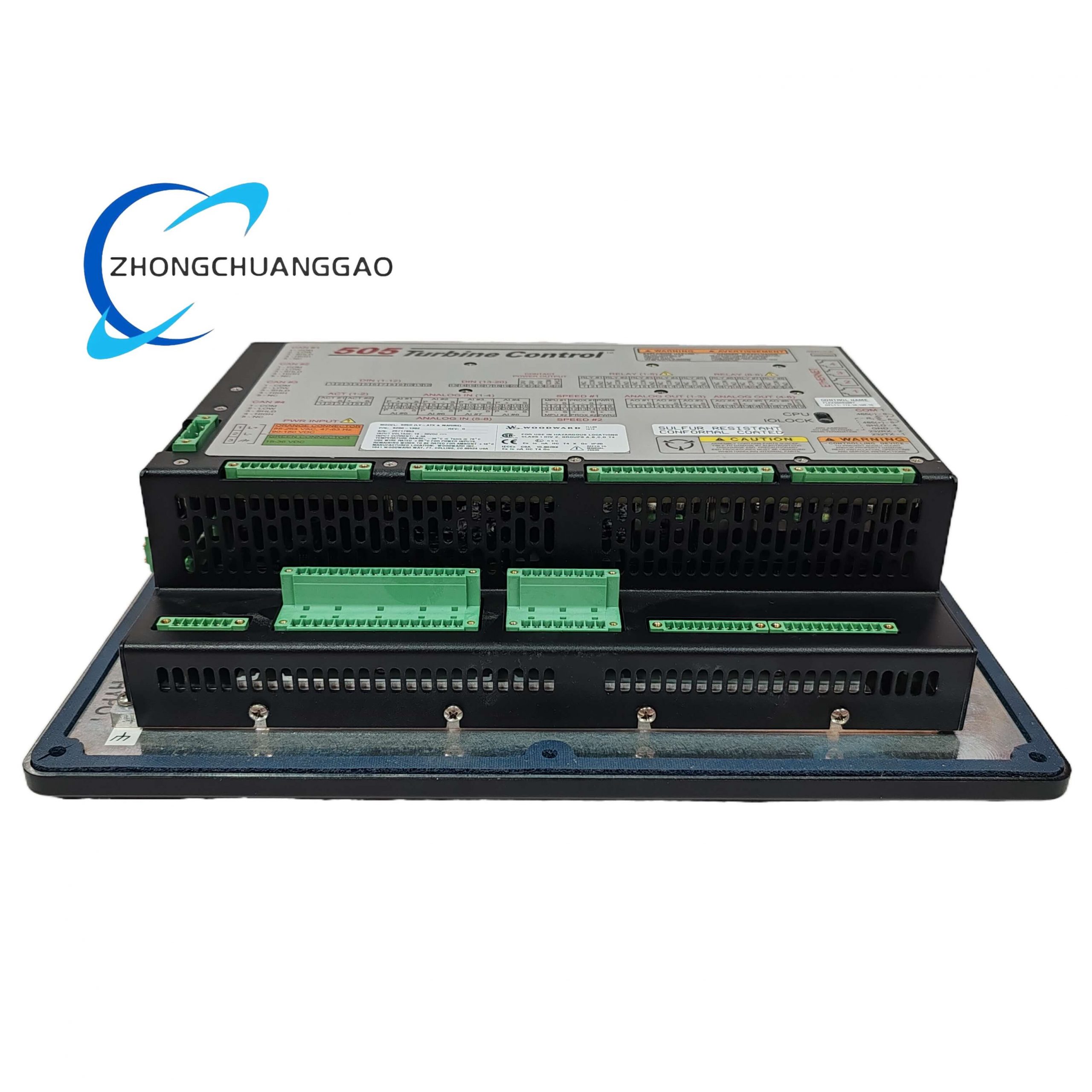
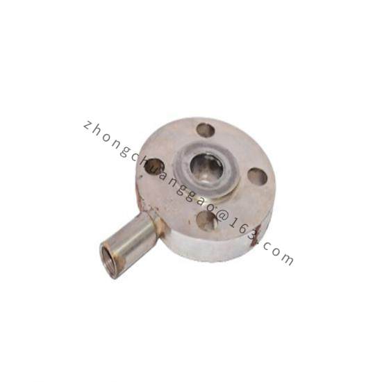
Structural Characteristics: Metal mechanical housing with mounting holes and central splined shaft; integrated digital driver electronics; 0.625-36 serrated tooth output shaft; optional rotation scale and indicator; multiple body sizes available.
-
Installation Requirements: Mount via base or flange to engine; align output shaft to driven linkage or directly couple to butterfly valve; connect 18–32 VDC power; wire analog/PWM/CAN command signals; configure and calibrate via RS-232 Service Tool before commissioning.
-
Usage Notes: Must be configured and calibrated for the specific engine application; use Woodward ProAct Service Tool and Watch Window Service software; avoid unauthorized modifications outside specified mechanical/electrical limits; handle PCB with ESD precautions; the digital driver current limiting protects against overheating.