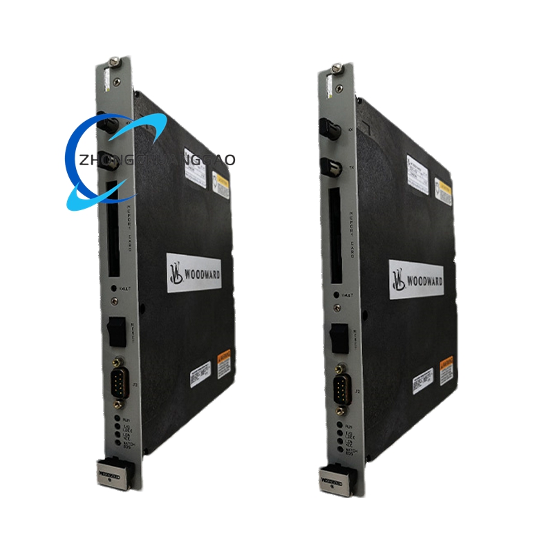
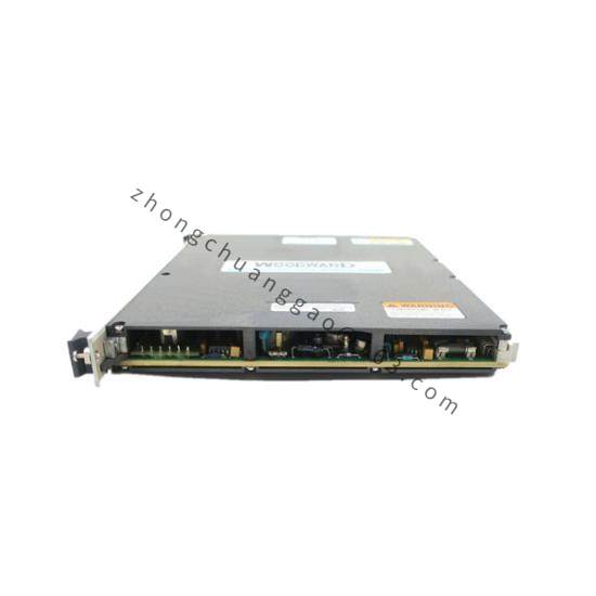

Woodward 9908-212
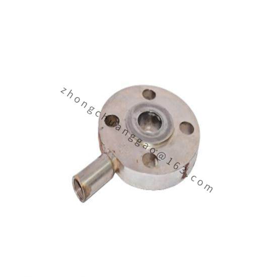
Product Overview: Woodward 9908-212 belongs to the Woodward LQ25 series of liquid fuel metering valves, designed for industrial and aeroderivative gas turbine engines, delivering excellent performance in the output power range of 6,000 kW to 42,000 kW. It is a bidirectional flow control valve that uses a throttling ΔP regulator, perfectly adapting to centrifugal or other pressure-source fuel pumping systems. It provides a reliable and cost-effective connection bridge between electronic engine control systems and gas turbines, and is widely used in power generation, mechanical drive, and marine fields.
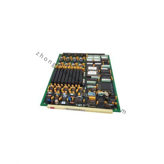
Detailed content
Technical Specifications:
-
Metering Ports Available: 0.1 in² (65 mm²), 0.2 in² (129 mm²), 0.3 in² (194 mm²)
-
Fuel and Ambient Temperature Options: -18 to +217°F (-28 to +103°C) or -40 to +217°F (-40 to +103°C)
-
IP Rating (per IEC 60529): IP66 (Conduit / No ID Module), IP64 (ID Module options)
-
Accuracy (% of port area): ±5% of actual or ±0.5% of maximum (greater of)
-
Metering Valve Full Travel Slew Time (closed loop position control): < 0.100 second
-
Metering Valve Shutdown Slew Time (at 24 Vdc to driver): < 50 ms
-
Position Loop Bandwidth: 35 rad/s (typical)
-
Fuel Connections: All ports: SAE J1926/1: 1-5/8-12
-
Overboard Vent Connection: SAE J1926/1: 7/16-20
-
Electrical Connections: Single Resolver / Conduit: 2x 1/2″-14 NPT; Dual Resolver / Conduit: 2x M25 x 1.5; Dual Resolver / ID Module: Connectors or 3x M25 x 1.5 Conduit
-
Assembly Weight: 49 lb (22 kg)
-
Vibration: Per MIL-STD-810-C
-
Fuel Viscosity: Must be between 0.5 and 12.0 centistokes
-
Fuel Cleanliness: Filtered to limit particulate size to 20 μm or smaller; water and sediment limited to 0.1% by volume; total particulate concentration limited to 2.64 mg per liter of fuel
Flow Performance by Port Size:
-
0.1 in² (65 mm²) port: Maximum fuel flow from 4,000 to 7,500 lb/h (1,814 to 3,402 kg/h)
-
0.2 in² (129 mm²) port: Maximum fuel flow from 8,250 to 15,000 lb/h (3,742 to 6,804 kg/h)
-
0.3 in² (194 mm²) port: Maximum fuel flow from 16,000 to 26,000 lb/h (7,258 to 11,794 kg/h)
Functional Features:
-
Rotary plate metering structure: Single moving part, high reliability
-
Non-contact position sensor: No mechanical wear, long service life
-
Rare-earth permanent magnet actuator: High torque density, fast response
-
Remote shutdown command input: Supports emergency stop
-
Valve/driver fault output: Facilitates system diagnostics
Material Composition:
-
Valve body and internal components: Made of corrosion-resistant materials
-
Seal system: Fluoroelastomer (FKM), suitable for various liquid fuels and temperature environments
-
Metering rotary plate: Corrosion-resistant shear-type metering component, positioned by high-torque actuator
Structural Features:
-
Core components: Rotary plate valve, electric actuator, non-contact position sensor, and throttle regulator. The rotary plate valve is integrated with the electric actuator to ensure precise flow control
-
Non-contact position sensors monitor valve position in real time to ensure control accuracy
-
Standard structure LQ25 valve body, configured with single-speed frameless resolver feedback device
-
Fuel inlet and outlet use SAE standard threaded connections; electrical interface is terminal block type
Working Principle: Liquid fuel flow control is achieved by precisely scheduling the port area of the metering valve and adjusting the pressure difference across the metering port. The rotary plate valve rotates under the drive of the electric actuator, changing the opening of the metering port to accurately control the fuel flow rate. The precision metering port on the rotary plate component, combined with sealing boots, accurately regulates the flow area over a large range. The throttle regulator maintains a stable differential pressure at the metering valve port. When the pressure differential at the metering valve port exceeds the set value, the regulator piston opens to bypass excess inlet flow back to the fuel pump inlet, ensuring the metering valve operates at a stable pressure differential, thus ensuring the accuracy of flow control. This pressure regulation system requires a positive displacement high-pressure fuel pump to be installed upstream of the LQ25 valve.
Application Scenarios:
-
Fuel control for gas turbine generator sets
-
Liquid fuel control for industrial mechanical drive systems
-
Liquid fuel control for marine propulsion systems
Installation Requirements: The LQ25 valve must be rigidly mounted to a rigid surface that does not exceed the vibration limits specified in the detailed specifications chapter. The inlet port receives pressurized fuel from the pump; the outlet line must be secured to the fuel line(s) going to the turbine combustors; the bypass line is connected back to the fuel tank. The overboard drain (OVBD) port must be connected via rigid steel piping to a fuel collection, purge, vent, or flare system so as not to be exposed to the hazard of blockage, physical damage, or back pressure higher than 69 kPa (0.69 bar/10 psig).
Usage Precautions:
-
Do not block the overboard drain, as this may cause fuel to enter the LQ25 actuator, resulting in danger with potential for personal injury and/or damage to the actuator
-
Leakage above 20 cm³/min from the overboard drain line indicates that the shaft seal in the LQ25 valve is worn or damaged, and should be investigated immediately
-
Special tools are required to replace the shaft seal; contact Woodward for technical assistance
-
The cabling for the power output from the driver to the actuator should be suitable for at least 90°C and 10°C above maximum fluid and ambient temperatures