Product Introduction: This model is explicitly identified in the official Woodward Installation and Operation Manual as “Oil Metering Valve 9908-002, 9908-300, and similar”. It is a Woodward hydraulic liquid metering valve designed for precise fuel flow control in industrial gas turbine applications.
Technical Specifications: Detailed technical parameters are covered in the official Woodward Oil Metering Valve Installation and Operation Manual (Publication covering 9908-002, 9908-300, and similar). The valve operates within the hydraulic liquid fuel and water valve platform which includes:
Application Scenarios: Industrial gas turbine liquid fuel metering; works with Woodward hydraulic control systems and actuators for fuel flow regulation.
Material Composition: Corrosion-resistant alloy and stainless steel construction; FKM sealing elements suitable for liquid fuel environments.
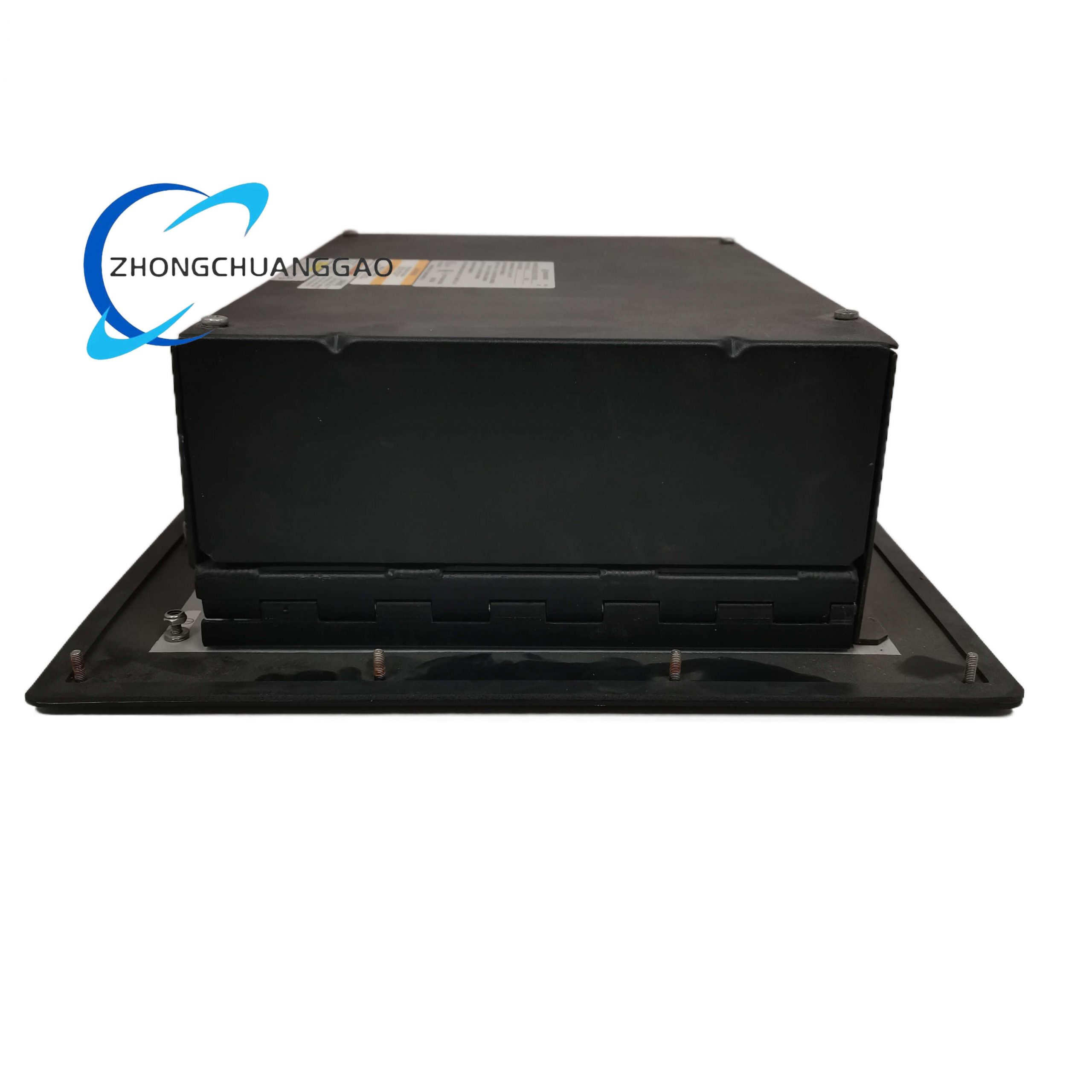
Structural Features: The valve consists of a dual coil electrohydraulic servo valve assembly, trip relay valve assembly, hydraulic filter assembly, and DC powered LVDT (DCDT) position feedback sensor. Outlined in Figures 1-1a and 1-1b for liquid fuel pilot or A/B metering valve (high-pressure version) and liquid fuel bypass valve (high-pressure version).
Working Principle: The hydraulic liquid metering valve uses a dual coil electrohydraulic servo valve assembly to control the position of the metering valve plunger. A DCDT position feedback sensor provides position feedback to the control system. The bypass valve section senses fuel pressures to maintain regulated differential pressure across the metering port, ensuring accurate fuel flow proportional to control command.
Installation Requirements:
Piping installation must follow hydraulic connection specifications
Proper rigging procedure using appropriate tools (LFV Piston Rig Tool as shown in Figure 3-2)
Fuel vent port must be properly connected
Electrical connections per controller wiring diagrams (Figures 1-4a through 1-4d)
Filter installation: V = 48 V (dc), Current = 15 mA, Conductance = 0 μF, Inductance = 0 mH
Comply with Machinery Directive 2006 requirements
Usage Precautions:
Read this entire manual and all other publications pertaining to the work before installing, operating, or servicing
Do not make unauthorized modifications outside specified mechanical, electrical, or operating limits
Unauthorized modifications constitute “misuse” and/or “negligence” within the meaning of the product warranty, excluding warranty coverage, and invalidate product certifications or listings
Practice all plant and safety instructions and precautions
Failure to follow instructions can cause personal injury and/or property damage