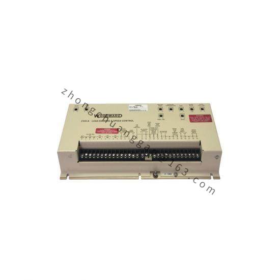
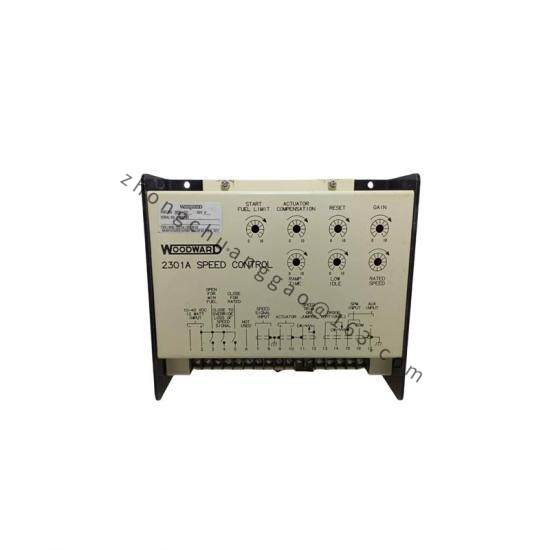
Product Name: 2301A Electronic Load Sharing and Speed Control (9907 Series)
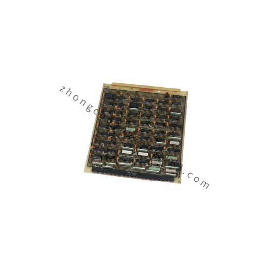
Product Overview: 9907-999 belongs to the Woodward 2301A family of electronic load-sharing and speed controllers for generator sets driven by diesel engines, gas engines, steam turbines, or gas turbines. The 2307/9907 platform is mounted in a sheet-metal chassis containing a single printed-circuit board with all potentiometers accessible from the front panel.
Actuator Output: 0–200 mA (typical for the 9907 series)
Power Supply: Low-voltage models 18–40 VDC (nom. 24 VDC); High-voltage models 90–150 VDC or 88–132 VAC
Forward / Reverse Acting: configurable by model
Isochronous & Droop control modes
Optional deceleration ramp (~20 s rated-to-idle when fitted)
Operating Temperature: –40 °C to +70 °C
Compliance: UL Listed E97763; EU Directive compliant (low-voltage models)
Functional Features: Provides simultaneous speed control and load sharing. Supports isochronous operation for isolated bus parallel running and droop operation for grid parallel or non-compatible governor paralleling. Adjustable idle/rated speed, start-fuel limiting, failed-speed-sensor protection, soft load transfer, Modbus® option, data logging, and dual serial ports (RS-232/RS-422).
Working Principle: Magnetic pickup (MPU) input from the prime mover gear provides speed frequency. The control compares actual speed to the reference and drives a proportional actuator (0–200 mA) to meter fuel. For load sharing, CT/PT signals feed the load-sharing bus so multiple units divide load proportionally.
Installation Requirements: Mount in a clean, ventilated panel away from direct engine heat and strong EMI. Provide a nearby, operator-accessible circuit breaker labeled as the unit isolating switch. Use shielded wiring with proper shield termination; route signal cables away from power conductors. Verify speed-range switch setting before energizing—wrong range may cause overspeed.
Application Scenarios: Standby and prime-power diesel generator stations, offshore platforms, oilfield power, marine power stations, and multi-unit parallel systems.
Usage Precautions: Read the entire 2301A instruction manual (Woodward manual 26006 / 82020) before installation. The prime mover must have an independent overspeed shutdown device. Observe ESD handling precautions—do not touch PCB traces; discharge body static before servicing.