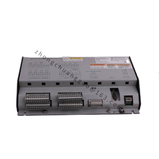
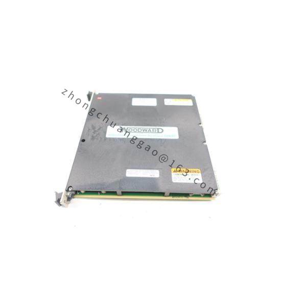
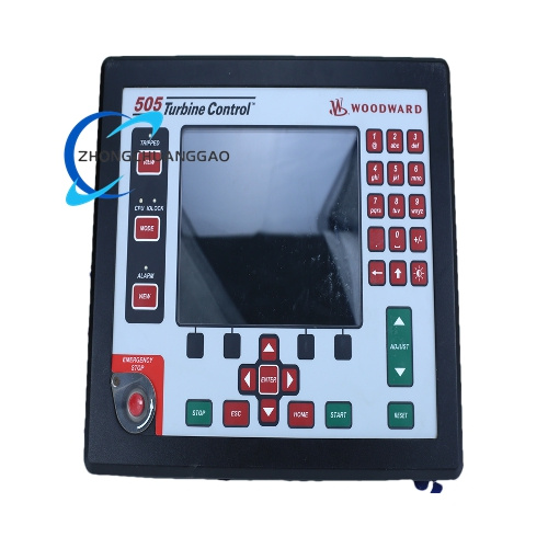
Product Name: Woodward 2301A Electronic Load Sharing and Speed Control
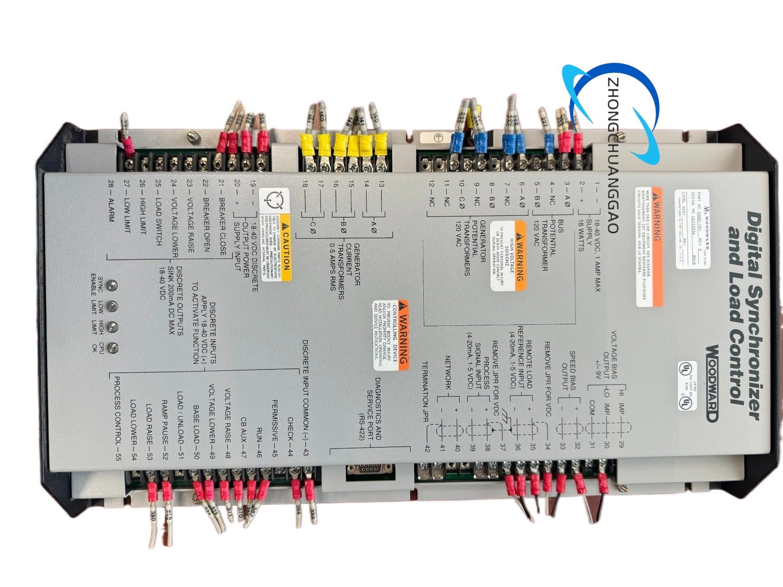
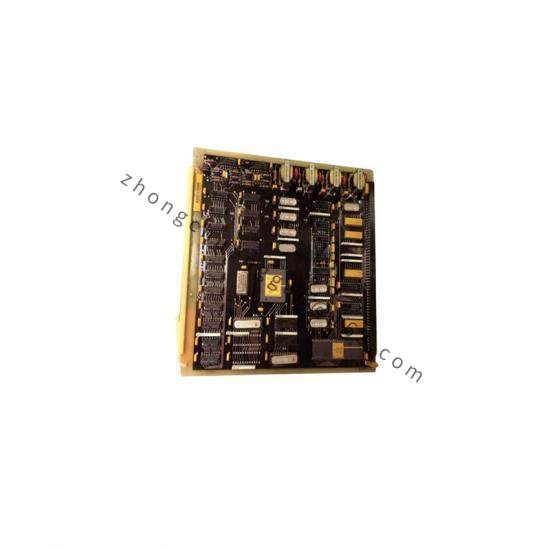
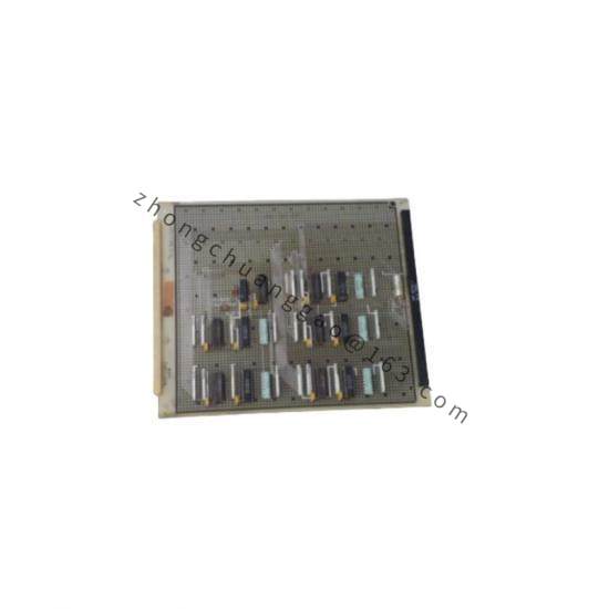
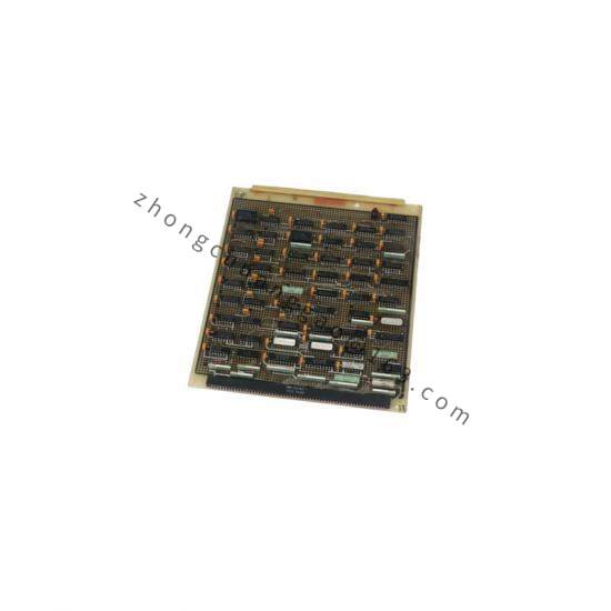
Product Overview: This model belongs to the Woodward 2301A 9907 series, providing electronic load sharing and speed control for generators driven by diesel or gasoline engines, or steam or gas turbines. The control is housed in a sheet-metal chassis with a single printed circuit board, all potentiometers accessible from the front.
Speed ranges (switch-selectable): 500 to 1500 Hz, 1000 to 3000 Hz, 2000 to 6000 Hz, 4000 to 12000 Hz
Power supply (high voltage): 90 to 150 Vdc or 88 to 132 Vac, 45 to 440 Hz
Power supply (low voltage): 18 to 40 Vdc
Actuator current range: 0 to 200 mA (typical for the series)
Forward or reverse acting configurations available
Single or tandem actuator compatibility
Operating temperature: -40 °C to +85 °C
Optional deceleration ramp: approximately 20 seconds from rated to idle speed (when option present)
Functional Features: Isochronous or droop mode control; switch-selectable speed ranges; forward/reverse acting; compatible with single or tandem actuators; minimum fuel contact; failed speed signal override; idle/rated ramp; actuator output 0 to 200 mA; external speed trim; speed and phase matching (SPM) synchronizer compatible.
Application Scenarios: Single prime mover operation; multiple prime movers on an isolated bus under Woodward load sharing control; base loading on an infinite bus; parallel operation of two or more prime movers.
Structural Characteristics: Sheet-metal chassis, single printed circuit board, all potentiometers front-accessible. The voltage class of the model is identified on the front of the control.
Working Principle: The controller receives speed input from a magnetic pickup and load input from current/potential transformers. It computes the required actuator drive signal to maintain isochronous speed or a droop characteristic. The actuator positions the fuel metering device proportionally. In reverse-acting systems, loss of actuator voltage drives the actuator to full fuel, allowing a backup mechanical governor to take control.
Installation Requirements: Install in an enclosed industrial control cabinet or closed electrical operating area. Provide adequate ventilation, maintenance clearance, and protection from water, condensation, vibration, and EMI. Must not be installed on the engine. Operating temperature range is -40 °C to +70 °C.
Usage Notes: Independent overspeed protection is mandatory. Before disconnecting batteries in systems with charging devices, turn off the charging device first. Observe ESD precautions when handling the printed circuit board. Verify the correct speed range is selected via switch S1 to prevent overspeed.