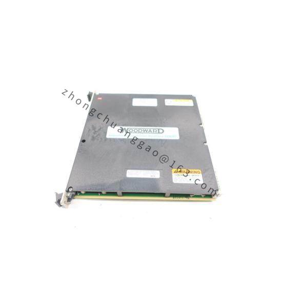
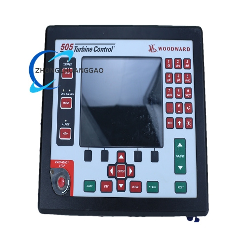
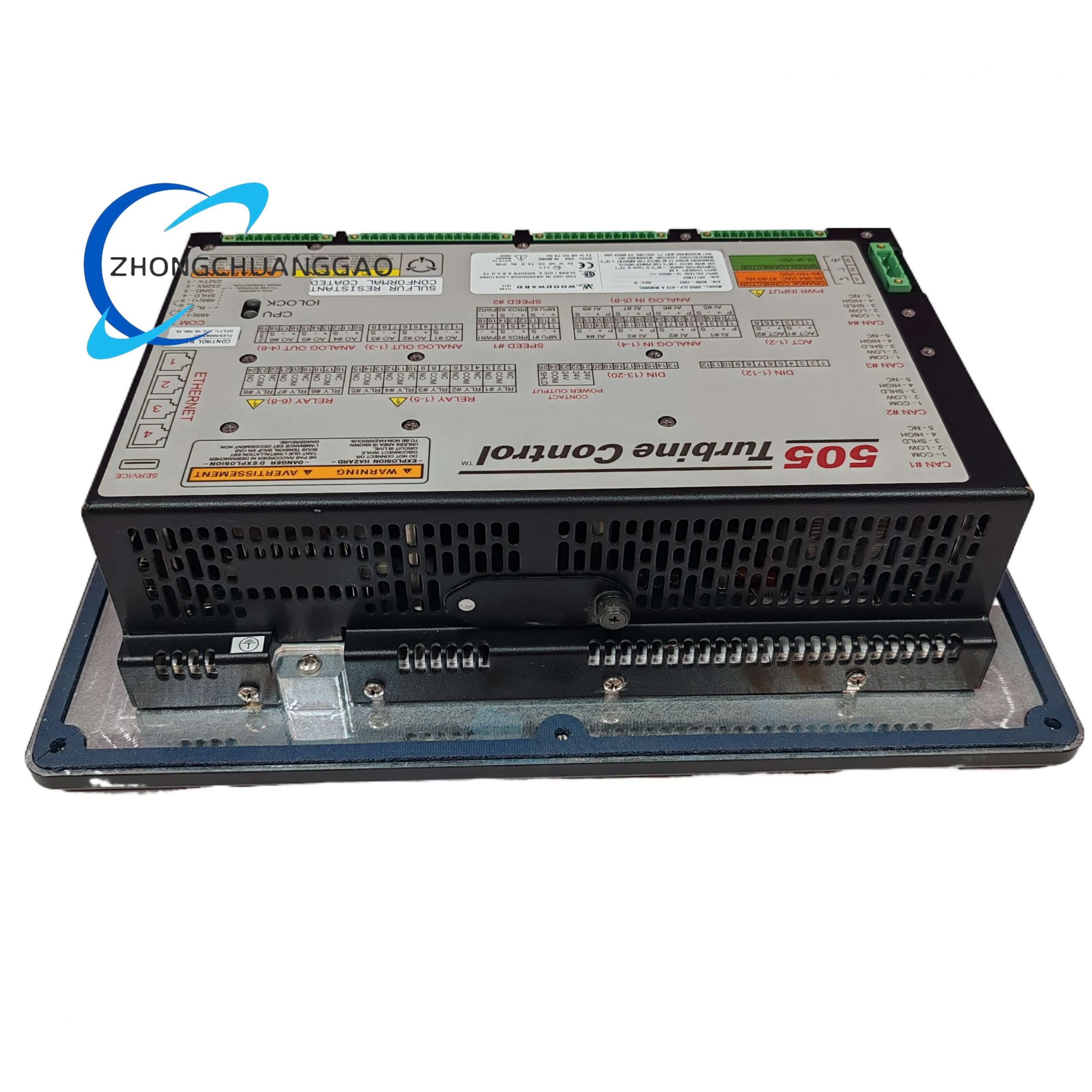
Woodward 9907-667
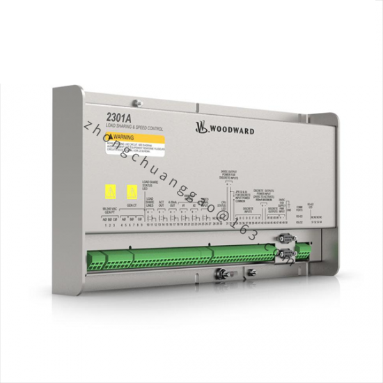
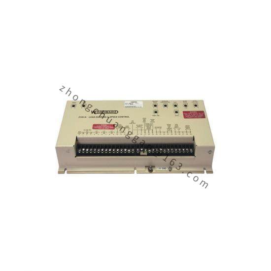
Product Name: 2301A Series Electronic Load Sharing and Speed Control (9905/9907 product line).
Product Introduction: The 9907-667 belongs to Woodward’s 2301A series of the 9905/9907 product line. This series of controllers is used to control load sharing and speed for generators driven by diesel engines, gasoline engines, steam turbines, or gas turbines.
Detailed content
Technical Specifications:
- Power Supply: Multiple voltage class models are available, including low-voltage models (20–40 Vdc) and high-voltage models (90–150 Vdc or 88–132 Vac).
- Speed Ranges (switch-selectable): 500–1500 Hz, 1000–3000 Hz, 2000–6000 Hz (factory default), 4000–12000 Hz.
- Control Mode: Supports Isochronous mode and Droop mode.
- Actuator Output: 0 to 200 mA, 30 to 45 Ω.
- Operating Temperature: -40 to +85 °C (-40 to +185 °F).
- Load Sharing Accuracy: Within ±5% of rated load with speed settings matched.
- Vibration: 4 Gs, 5 to 500 Hz. Shock: 60 Gs.
- Weight: Approximately 1.8 kg (4 lb).
Functional Features:
- Core function is to simultaneously implement the two major functions of speed control and load sharing.
- Speed control maintains stable speed of the prime mover (engine/turbine).
- Load sharing ensures proportional load sharing when multiple units operate in parallel, avoiding single-unit overload or uneven load distribution.
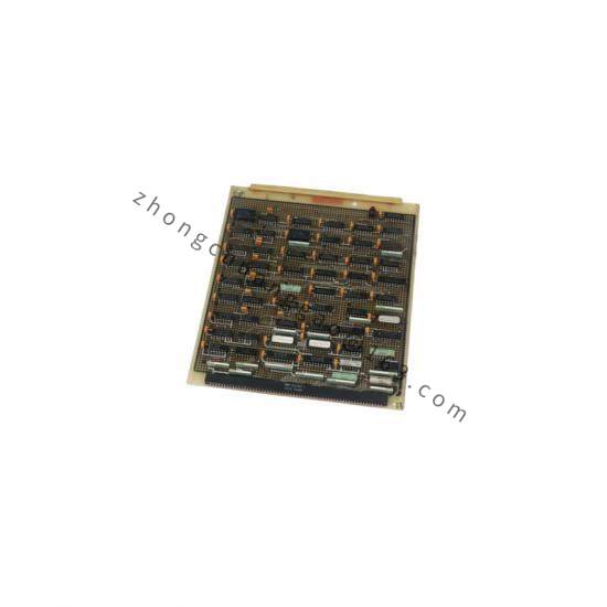
- The controller is housed in a sheet-metal chassis and consists of a single printed circuit board.
Application Scenarios: Load sharing and speed control for diesel generators, gasoline generators, steam turbine power generation, and gas turbine power generation.
Working Principle: Through an electronic control circuit, it monitors generator output and prime mover speed signals, automatically adjusting the fuel supply of each unit to achieve balanced load distribution during parallel operation.
Material Composition & Structural Features (applicable to the 2301A 9905/9907 series):
- Enclosure: Sheet-metal chassis with a gloss powder finish.
- Internal Structure: Consists of a single printed circuit board; all potentiometers are accessible from the front of the chassis.
- Electronic components: Static-sensitive parts. Avoid all plastic, vinyl, and Styrofoam (except antistatic versions) around printed circuit boards. Do not touch the components or conductors on a printed circuit board with your hands or with conductive devices.
Installation Requirements:
- Location: Avoid installing directly on the engine. Keep away from water, vibration sources, and strong electromagnetic interference equipment.
- Power Requirements: Low-voltage type requires 18–40 VDC; High-voltage type requires 90–150 VDC or 88–132 VAC.
- Wiring: Use shielded wiring. The speed sensor (magnetic pickup) requires a minimum signal of 1.0 Vrms at starting speed, and the gap between the sensor and the gear should be controlled between 0.25–1.0 mm.
- Electrostatic Discharge Awareness: Discharge body static before handling the control (with power to the control turned off, contact a grounded surface and maintain contact while handling the control).
Usage Precautions:
- Overspeed Protection: The engine, turbine, or other type of prime mover should be equipped with an overspeed shutdown device to protect against runaway or damage to the prime mover. The overspeed shutdown device must be totally independent of the prime mover control system.
- Battery Charging: To prevent damage to a control system that uses an alternator or battery-charging device, make sure the charging device is turned off before disconnecting the battery from the system.
- Potentiometer Adjustment: The Rated Speed potentiometer is the only multi-turn pot in this control. All other pots are single-turn. Take care not to turn these pots beyond their stops.
- Proper Use: Any unauthorized modifications to or use of this equipment outside its specified mechanical, electrical, or other operating limits may cause personal injury and/or property damage, and will void the product warranty and certifications.