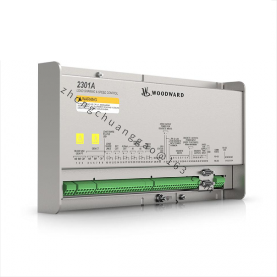
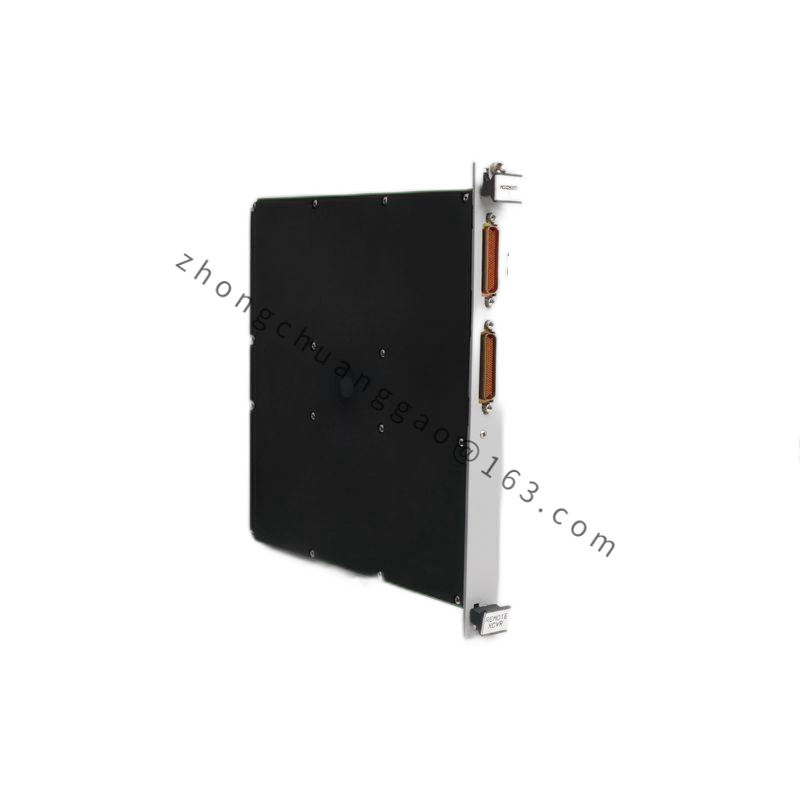
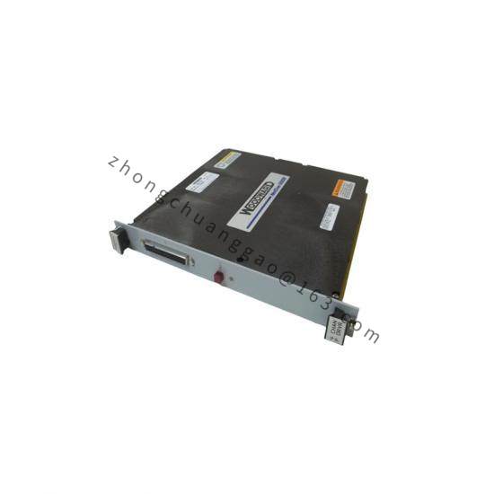
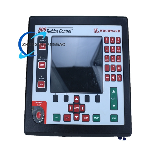
Product Name: 2301A Electronic Load Distribution and Speed Controller (9907 Series)
Product Introduction: The 9907-606 belongs to Woodward’s 2301A 9907 series of microprocessor-based electronic controllers designed for speed control and load distribution of turbines, engines, and other prime movers. It simultaneously performs speed governing and load sharing to ensure stable operation during standalone or parallel operation.
Speed ranges: 500–1500 Hz, 1000–3000 Hz, 2000–6000 Hz, or 4000–12000 Hz (selectable via Switch S1)
Actuator output: 0–200 mA
Voltage levels: Low voltage 18–40 VDC; High voltage 90–150 VDC or 88–132 VAC
Speed sensor: Magnetic pickup, minimum 1.0 Vrms at starting speed, maximum 25 Vrms at rated speed
Sensor-to-gear air gap: 0.25–1.0 mm
Operating temperature: –40 to +85 °C
Relative humidity: 10%–95% (non-condensing)
Functional Features:
Dual-mode control: Isochronous (constant speed) and Droop mode (speed decreases proportional to load)
Load distribution ensuring proportional load sharing among paralleled units
Forward/reverse acting configurations available
Compatible with 0–200 mA actuators
Application Scenarios: Steam turbines, gas turbine generator sets, turboexpanders, compressor and pump mechanical drives, marine propulsion, offshore platform power generation.
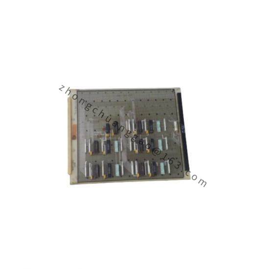
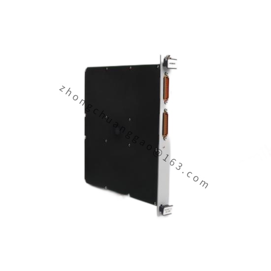
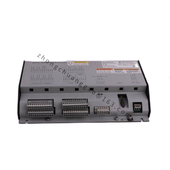
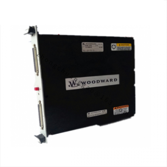
Structural Characteristics: Front-panel terminal concentration; printed circuit board construction housed in a metal enclosure suitable for control panel integration; vertical mounting with inclination ≤ ±45° (without forced ventilation).
Working Principle: The magnetic speed sensor detects prime mover rotational frequency, the controller compares actual speed with the setpoint, and outputs a 0–200 mA signal to the actuator to adjust fuel or steam flow, forming a closed-loop speed control. In parallel operation, the load distribution logic proportionally shares load among multiple units.
Installation Requirements:
Do not install directly on the engine
Maintain ventilation clearance ≥ 3 cm; distance from heat sources ≥ 15 cm
Install an XT-FIL-1/2 anti-interference filter for high-voltage types (mandatory in marine applications)
Keep away from water, vibration sources, and strong electromagnetic interference
Usage Precautions:
Ensure independent overspeed trip protection is provided on the prime mover
Verify actuator current direction (forward/reverse) matches the application before commissioning